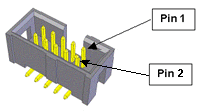
For controllers equipped with a MCIM, these boards provide two or four general purpose analog input channels that are conveyed though a single connector. See Figure 7-43.
The Analog to Digital Converter has a 12-bit resolution and a conversion delay of 3.2 microseconds per channel. The ADC channels are continuously scanned in sequence, so a new reading is available for each channel every 6.4 microseconds (for two channel boards) or 12.8 microseconds (for four channel boards). The input impedance of the analog conversion circuit is 20,000 ohms. There is a 4 KHz noise filter on each input.

Table 7-35 details the pinout for the analog input connector.
| Pin | Description |
|---|---|
|
1 |
24VDC |
|
2 |
24VDC |
|
3 |
24VDC |
|
4 |
24VDC (+/- 10VDC input signal, channel 3 on selected controllers) |
|
5 |
GND |
|
6 |
+/- 10VDC input signal, channel 2 |
|
7 |
GND |
|
8 |
+/- 10VDC input signal, channel 1 |
|
9 |
GND |
|
10 |
GND (+/- 10VDC input signal, channel 4 on selected controllers) |
|
User Plug Part No |
AMP 746285-1 or Molex 22-55-2101 or 90142-0010. For the Molex plug, use Molex pins 16-02-0103 and Molex crimp tool 63811-1000. |