
When referring to digital input and output signals, "sinking" and "sourcing" indicates whether the external equipment or the controller provides current to power the signaling operation. The selection of sinking or sourcing is controlled by a series of hardware jumpers (Figure 7-57) on the communication board.
For digital inputs, if the controller is "sinking," the external equipment must connect the input signal to a voltage to indicate a logical high value. This configuration is compatible with "sourcing" (PNP) sensors. If the controller is "sourcing," the external equipment must connect the input signal to ground to indicate a logical high value. This configuration is compatible with "sinking" (NPN) sensors.
The digital input signals can be configured as sinking or sourcing in groups of four signals. This configuration is performed using three sets of three jumper posts labeled J4, J5, and J6. The locations of these posts are illustrated in the diagram of the communication boards and are identified by stenciled labels on the surface of the boards.
NOTE: As shipped from the factory, all digital inputs are normally configured as "sourcing."
Table 7-41 indicates how the pins of each set of posts must be shorted ("jumpered") in order to achieve the specified configuration. For the MIDS3 (G2xxxC controllers), pins 1 are closest to the edge of the board. For the MCIM (G3xxx and G2xxxB controllers), pins 1 are closest to the center of the board.
| Digital Input Signals | For Sinking Inputs | For Sourcing Inputs |
|---|---|---|
|
Inputs 1 TO 4 |
J4-3 TO J4-2 |
J4-2 TO J4-1 |
|
Inputs 5 TO 8 |
J5-3 TO J5-2 |
J5-2 TO J5-1 |
|
Inputs 9 TO 12 |
J6-3 TO J6-2 |
J6-2 TO J6-1 |
For digital outputs, if the controller is "sinking," the external equipment must connect the output signal to a pull-up voltage. This
configuration is compatible with "sourcing" (PNP) devices. If the controller is "sourcing," the external equipment must connect the signal to a pull-down to ground. This configuration is compatible with "sinking" (NPN) devices.
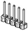
The digital output signals can be individually configured as sinking or sourcing. This configuration is performed using a block of eight rows of jumper posts (Figure 7-58), five pins per roll, labeled J7. The locations of these posts are illustrated in the diagram of the communication boards and are identified by stenciled labels on the surface of the boards.
NOTE: As shipped from the factory, all outputs are configured as "sinking."
For the MIDS3 board (G2xxxC controllers), the row closest to the Ethernet connector is for DOUT8. For the MCIM board (G3xxx and G2xxxB controllers), the row closest to the Ethernet connector is for DOUT 1. For both the MIDS3 and the MCIM, within each row, pins 1 are closest to the edge of the board and pins 5 are closest to the center of the board. See Table 7-42.
| Digital Output Signals | For Sinking Outputs | For Sourcing Outputs |
|---|---|---|
|
One row of 5 pins |
Pins 2 TO 3 and 4 TO 5 |
Pins 1 TO 2 and 3 TO 4 |
Digital output #1 (DOUT1) formerly drove 500mA of current on all controller models when configured as sourcing, whereas digital outputs 2-8 drive 100mA. When configured for 500mA, even when the output signal is off, a small amount of current leaks. This leakage can cause some devices that are connected to this signal to always indicate that this output is on unless a drainage resistor is added.
In early 2013, the MIDS3 (G2xxxC Controllers only) was modified to add three sets of three jumper posts, labeled J16, J17, J18, that configure whether DOUT1 drives 500mA or 100mA. The locations of these posts are illustrated in the diagram of the communication boards and are identified by stenciled labels on the surface of the boards.
NOTE: As shipped from the factory, DOUT1 is configured to drive 100mA on G2xxxC Controllers.
For each jumper, pin 1 is closest to the center of the board and pin 3 is closest to the edge of the board. See Table 7-43.
| Digital Output #1 Current Output |
100 mA | 500 mA |
|---|---|---|
|
J16, J17, J18 |
Pins 2 TO 3 |
Pins 1 TO 2 |