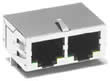

In order to simplify networking equipment together via Ethernet, the Guidance Controllers contain two 10/100 BaseT Ethernet RJ45 connectors (four ports are available as a special order). Any of the ports can be utilized with either a straight-thru or a cross-over Ethernet cable to connect to other equipment. See Figure 7-59 and Figure 7-60
|
|
|
All of the ports are interfaced to a built-in 10/100 Mbit Ethernet Switch that auto detects the sense of each cable. If two ports are connected to equipment that are communicating with each other but not the controller, the Ethernet switch automatically routes the traffic between the two ports and does not send this information to the controller. For example, if an Ethernet camera is connected to one port and a PC is connected to another port, the camera image data will not burden the controller's CPU.
See the Setup and Operation Quick Start Guide for instructions on setting the IP address for the controller.