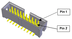
The remote front panel interface includes all of the signals necessary to implement a fully compliant EC Category 3 (CAT-3) Safety front panel that includes a Manual Control Pendant. In particular, this connector provides signals (including redundancy as necessary) for implementing an E-Stop circuit, an auto/manual switch, a high power "on" button with a high power "on" indicator lamp, and a RS-232 interface to a Manual Control Pendant.
In the future, Brooks will offer a Remote Front Panel option that plugs into this connector. Alternatively, customers can develop their own custom front panels (see the section on "Safety Circuits For Remote Front Panel" for a suggested design). Or, if the user's application does not require a fully compliant Category 3 (CAT-3) front panel, the controller can be operated without a front panel or with only a simple E-Stop button or a Manual Control Pendant with an E-stop button.
When a front panel is not utilized, the following pins on the front panel connector must be jumpered in order for the controller to operate properly. (The controller is shipped with these jumpers installed.)
1-2, 3-4, 5-6, 7-8, 9-10, 11-12, 13-14
If a Manual Control Pendant is not connected to the secondary RS-232 port provided in this connector, this serial interface can be accessed via a GPL procedure as device /dev/com2 for general communications purposes. See Figure 7-61 and Table 7-44.
NOTE: Unlike the primary serial interface, this secondary serial interface does not support flow control.

| Pin | Description |
|---|---|
|
1 |
Auto/Manual 2 (If no front panel or Auto/Manual switch, connect to pin 2). Input signal that is high to indicate that the system is being operated in a fully automatic mode or low or open for manual operation. This is normally controlled by a key switch on the Remote Front Panel of the master controller. During Manual Mode, only Jog mode motions are permitted and the servos restrict the axes to special "Manual mode max torque %" and "Manual mode speed limits" to ensure that the system can be safely manually operated. When this signal changes from Auto to Manual, motor power is automatically turned off and must be re-enabled to move the robot. The Auto/Manual signal is daisy chained to all controllers in the servo network. |
|
2 |
24VDC |
|
3 |
Auto/Manual 1 (If no front panel or Auto/Manual switch, connect to pin 4). Redundant Auto/Manual input signal. |
|
4 |
24VDC |
|
5 |
ESTOP_L 2 (If no front panel or E-Stop not asserted, connect to pin 6). An input signal that is low or open indicates that a hardware E-Stop condition has been asserted by some source. Set high if no E-Stop condition is asserted. The controller hardware will not permit motor power to be enabled when an E-Stop condition exists. |
|
6 |
Force ESTOP_L. Output signal that, when low, indicates that the Remote Front Panel should force ESTOP_L 1 and ESTOP_L 2 to be asserted (low). The System Software toggles this signal low at startup to verify that the ESTOP_L 1, ESTOP_L 2, and External ESTOP circuits are properly working. The System Software also uses this as a means for asserting a hardware E-Stop condition during normal operation. This signal is normally held high. |
|
7 |
ESTOP_L 1 (If no front panel or E-Stop not asserted, connect to pin 8). Redundant ESTOP input signal. |
|
8 |
Force ESTOP_L. Redundant Force ESTOP_L output signal. |
|
9 |
External ESTOP_L (If no front panel or not an External ESTOP, connect to pin 10). Diagnostic input signal that is low when an E-Stop is generated from an external source. This allows the System Software to display different error messages to alert the operator as to the source of the E-Stop condition. |
|
10 |
Force ESTOP_L. Redundant Force ESTOP_L output signal. |
|
11 |
High Power Lamp Fail (If no front panel, jumper to pin 12). Input signal that is set high or open if the Remote Front Panel lamp, which indicates when motor power is enabled, has failed. When this signal is high, motor power cannot be enabled. |
|
12 |
Ground |
|
13 |
High Power Enable (If no front panel, jumper to pin 14). Input signal that must transition from low to high during the EC Category 3 (CAT-3) power enable sequence to request that motor power be enabled. This is normally connected to a momentary press the Enable power button on the Remote Front Panel. |
|
14 |
Ground |
|
15 |
Spare |
|
16 |
High Power Status. Output signal that is asserted (high) when high power to the motor is enabled. This is typically connected to a relay that turns on the High Power Lamp in the Remote Front Panel. |
|
17 |
MCP RXD. RS-232 receiver serial line from the Manual Control Pendant or external device. |
|
18 |
MCP TXD. RS-232 transmitter serial line to the Manual Control Pendant or external device. |
|
19 |
5VDC. |
|
20 |
5VDC. WARNING - This voltage is provided as a convenience but is limited in the current that can be supplied. Drawing excessive current can damage the controller. Consult Brooks if there is any question about the use of this voltage. |
|
User Plug Part No |
Amp 746285-4 or Molex 22-55-2201 or Molex 90142-0020. For the Molex plugs, use Molex pins 16-02-0103 and Molex crimp tool 63811-1000. |