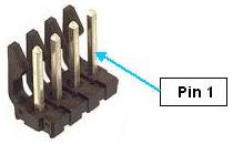
This is a four-pin header (Figure 7-62) that is used to: (1) output signals that control turning on and off the external motor power supply and (2) input the 24VDC that powers the digital section of the controller. If a user purchases a PrecisePower Intelligent Motor Power Supply, Low Voltage Power Supply, and the Power Harness, there is a single cable that plugs into this header.
The motor "power on" signals are configured as a redundant pair of sinking signals. These should be wired to a pair of relays that are connected in series to enable and disable the motor power supply. Normally, 5 to 24VDC is applied to this control circuit. The external motor power supply should be turned on when the controller's logic switches the "power on" signals to ground. These signals are automatically opened when an E-Stop or other condition occurs that requires that the amplifiers be shutdown.
The 24VDC power input and ground pins should be connected to a low voltage power supply that remains on independently of whether the motors are enabled. Turning off the 24VDC will completely shutdown the controller.
The mating plug for this header is a Molex 09-50-3041 and the crimp style pins for this connector are 08-50-0105. Table 7-45 shows the pin designations for this plug.
| Pin | Description |
|---|---|
|
1 |
GND |
|
2 |
+24VDC input |
|
3 |
Motor power enable. Switched to ground when power is being enabled. Capable of sinking 2A at 24VDC. |
|
4 |
Motor power enable (Redundant signal). Provided to comply with safety standards. |
|
User Plug Part No |
Molex 09-50-3041. For this Molex plug, use Molex pins 08-50-0105 and Molex crimp tool 63811-2200. |