Open topic with navigation
HVPA/LVPA Motor/Brake Interfaces
There are identical motor/brake connectors located
on the High Voltage Power Amplifiers (HVPA) of the Guidance 3000 (excluding
the 30A version, see below), the 4-axis High Voltage Power Amplifier
(4AHV) for the Guidance 2000, and the two-Axis Slave High Voltage Power Amplifier (2AHV) for the Guidance 2600. Each
HVPA has two motor drivers per board with two connectors mounted at the top
edge. Each
4AHV has four motor drives with a connector mounted at each corner. Each 2AHV has two motor drives with a connector at each corner of the high side of the sheet metal. These
connectors are numbered on their tops and are illustrated in Figure 11-29, Figure 11-30, and Figure 11-31 for each type
of controller.
|
The High Voltage Power Amplifiers (HVPA/_AHV) and the Motor/Brake
connectors and their leads contain unshielded high voltage pins,
components and surfaces. It
is intended that the Guidance Controllers with these components be
mounted in a cabinet or machine chassis that is not accessible when
AC line power is turned on.
|

|
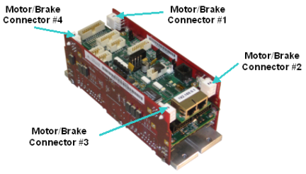
Figure 11-29: Motor/Brake Connectors
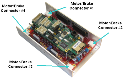
Figure 11-30: Motor/Brake Connector
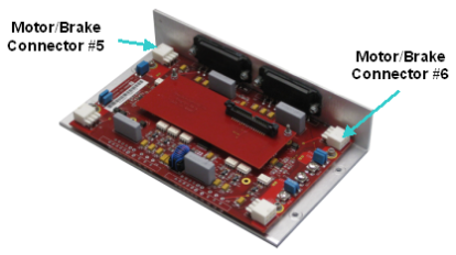
Figure 11-31: Motor/Brake Connectors
Mating plugs and pins for the motor/brake
connectors are shown below (Figure 11-32 and Table 11-19).
NOTE: Although all of the motor/brake
connectors have a brake signal, this is only provided as a wiring convenience. The
Guidance Controllers turn all brakes on and off at one time, so
independent brake control for each motor is not supported via the dedicated
IO lines available in this connector. If required, individual brake
control can be implemented using general purpose digital output signals.
Figure 11-32: Mating Plug
|
While
many brakes draw less than 0.5A, for some large motors, the current
draw can be much larger. If more than 2A is required for all
brakes, an external relay should be used to separately power the brakes
to avoid damaging the controller.
|

|
Table 11-18: Pinout
| Pin |
Description |
|
1
|
Brake Power 24VDC, maximum current 2A total for all brakes
|
|
2
|
Motor Phase V
|
|
3
|
Motor Phase W
|
|
4
|
Brake Power Return
|
|
5
|
Motor Frame Ground/Cable Shield
|
|
6
|
Motor Phase U
|
|
Board Connector Part No
|
AMP Mini Universal Mate-N-Lok 2 6 pin 770969-1
|
|
User Plug Part No
|
Amp 794190-1 (pins AMP 794231-1)
|
|
User Socket Part No
|
Amp 794231-1 for 16-20 gauge wire
|
|
Crimp Tool
|
Amp 91594-1
|
The 30A version
of the Guidance 3400 controller, the Guidance 3430, utilizes a different
motor/brake connector that can support larger gauge wires and higher motor
currents. Each
of the High Voltage Amplifier (HVPA2) boards has two motor
drives and two connectors mounted on the side of the board. Figure 11-33 shows the
numbering for the motor/brake connectors.
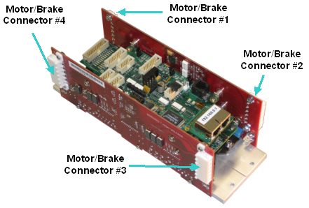
Figure 11-33: Numbering for Motor/Brake Connectors
|
The High Voltage Power Amplifiers and the Motor/Brake
connectors and their leads contain unshielded high voltage pins,
components and surfaces. It
is intended that the Guidance Controllers with these components be
mounted in a cabinet or machine chassis that is not accessible when
AC line power is turned on.
|
|
Mating plugs and pins for the motor/brake connectors
are shown in Figure 11-34 and Table 11-19.
NOTE: Although all of the motor/brake
connectors have a brake signal, this is only provided as a wiring convenience. The
Guidance Controllers currently turn all brakes on and off at one time, so
independent brake control for each motor is not supported via the dedicated
IO lines available in this connector. If required, individual brake
control can be implemented using general purpose digital output signals.
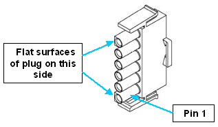
Figure 11-34: Mating Plugs & Pins
Table 11-19: Pinout
| Pin |
Description |
|
1
|
Motor Phase W
|
|
2
|
Motor Phase V
|
|
3
|
Motor Phase U
|
|
4
|
Motor Frame Ground/Cable Shield
|
|
5
|
Brake Power Return
|
|
6
|
Brake Power 24VDC, maximum current 2A total for all brakes
|
|
Board Connector Part No
|
Tyco Electronics 640587 Universal Mate-N-Lok
|
|
User Plug Part No
|
Tyco Electronics 640585 6 Circuit Universal Mate-N-Lok
|
|
User Socket Part No
|
AMP 350550-1 for 14-20 gauge wire
|
|
Crimp Tool
|
AMP 90546-1
|