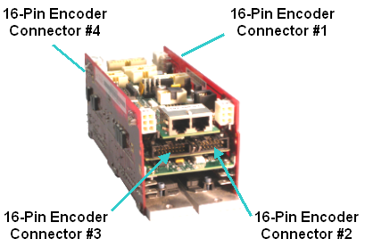
There are four identical 16-pin encoder connectors on the MIDS board for the Guidance 3000 and the MIDS3 for the Guidance 2000C. There are two encoder connectors mounted on each end of these boards. These connectors are numbered in the same order as the labeled motor connectors. The following illustrates the positions of the encoder connectors in both controllers. See Figure 7-80 and Figure 7-81.
Figure 7-80: 16-pin Encoder Connector #3 & #2
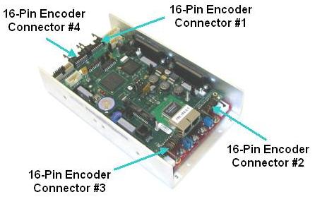
Figure 7-81: 16-pin encoder connectors #1, #2, #3, and #4
The encoder connectors are configured so that a variety of incremental or absolute encoders can be connected to the controller. Pins 2, 3, 5, 6, 8 and 9 will accept either a standard digital or an optional analog sin wave encoder signal (only supported in selected controller models). For analog encoder signals, an optional 12-bit ADC is used to digitize the signals. This ADC can also interpolate the analog encoder signals to increase the effective resolution of the encoder. Absolute encoders are interfaced via these same signal pins. (See Third Party Equipment for information on connecting supported absolute encoders.) Either single-ended or differential encoder signals can be connected to this primary encoder interface. (Analog and absolute encoder interfaces are only available on some "Enhanced" versions of the Guidance Controllers due to special hardware requirements.)
In addition to the primary encoder interface, there are three digital inputs available in each encoder connector. These can be configured for hall-effect sensors or two over-travel sensors plus a homing sensor. When configured for these functions, they should be treated as standard 5VDC sourcing digital inputs connections. Alternatively, these three digital signals can interface to a second, single-ended encoder. This single-ended encoder can be used independently of the primary encoder or the two encoders can be used together to implement dual encoder loop servo control of an axis of motion. See Figure 7-82.
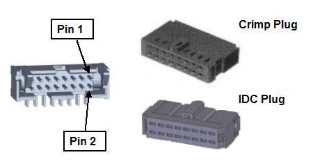
Figure 7-82: Encoder Connector & Plugs
Table 7-54 defines the connector pinout. The second column should be used when the three digital inputs are configured for hall-effect sensors or over-travel switches and a homing sensor. The third column describes the pinout when a second, single-ended encoder is utilized.
| Pin | 3 Digital Inputs (5VDC) |
2nd Encoder (5VDC) |
|---|---|---|
|
1 |
Gnd |
|
|
2 |
Encoder 1 A+ (Digital or Analog) |
|
|
3 |
Encoder 1 A- (Digital or Analog) |
|
|
4 |
5VDC provided to power encoders. The sum of the current drawn from all four encoder connectors is limited to 1 amp. |
|
|
5 |
Encoder 1 B+ (Digital or Analog) |
|
|
6 |
Encoder 1 B- (Digital or Analog) |
|
|
7 |
Gnd |
|
|
8 |
Encoder 1 Z+ (Digital) |
|
|
9 |
Encoder 1 Z- (Digital) |
|
|
10 |
Gnd |
|
|
11 |
Digital Input #1 |
Encoder 2 A+ |
|
12 |
Gnd (Reserved for Abs Encoder Bat Gnd) |
|
|
13 |
Digital Input #2 |
Encoder 2 B+ |
|
14 |
Vcc (Reserved for Abs Encoder Bat Pwr) |
|
|
15 |
Digital Input #3 |
Encoder 2 Z+ |
|
16 |
Gnd |
|
|
Board Header |
Amp 104315-03-3-o-s |
|
|
Crimp Plugs |
Amp 102387-3 or Molex 90142-0016. For the Amp plug, use Amp pins 102128-1 and AMP crimp tool 91517-1. For the Molex plug, use Molex pins 16-02-0103 and Molex crimp tool 63811-1000. |
|
|
Alternate IDC Plug |
Amp 746285-3 |
|