The DIO Motion's provide an extremely easy method for training the robot to execute a simple, repetitive sequence of motions. Once trained, individual motions or groups of motions can be initiated based upon the value of a hardware or software digital input signal (DIN). For example, this method can be used to move the robot in response to signals from a Programmable Logic Controller (PLC).
The setup panels below are all that is needed to teach the DIO Motion sequences. The execution of DIO Motion is controlled by the standard Operator's Control Panel.
For a step-by-step example on how to program a robot using MotionBlocks, see Setup and Operation Quick Start Guide > Motion Blocks Programming.
| DIO Motions | Description |
|---|---|
|
Motion management |
This panel provides the basic setup and status information for DIO motion mode. See the reference area for details on the defined DataIDs. |
|
Motion block setup |
This panel provides an interface for setting up to 20 motion blocks. Each motion block can be configured to move the robot to a location based on when a specified input is triggered. For detailed information on the DataIDs used to configure the motion blocks please see the reference area. See the illustrations below and the accompanying table for how the setup panel operates. |
|
Motion block Debug |
If the Auto Execution trace enable DataID is TRUE, all motion block items will be displayed in their raw form. This is used for debugging the system. It is suggested that you normally use the Motion block setup panel (shown below) for configuring the motions. |
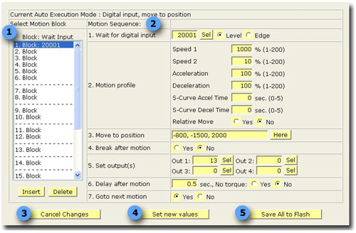
Motion Block Setup
| Motion Block Setup | Description |
|---|---|
|
1. Motion block navigation. |
List of available motion blocks. Selecting the desired motion block will update the values to the right. |
|
2. Motion Sequence |
1. Wait for digital input: A single digital input channel number can be entered or selected. When this signal is triggered, the selected motion will be performed. The motion is triggered based on either an edge transition or level value.
2. Motion Profile: The motion speed, acceleration, deceleration, s-curve profile and type of motion for the specified motion block are defined in this section.
3. Move to position: You can manually enter the robot coordinates or click on the 'Here' button. This button will take the current position of the robot and place it in the data field.
4. Break after motion: If enabled, will cause the robot to come to a complete stop before setting the output signals or moving to the next position.
5. Set output(s): Up to 4 digital output signals can be fired when the end of the specified motion block is reached. These are normally used for end of arm tooling (gripper or actuators).
6. Delay after motion: After the motion is completed and any defined outputs are fired, this delay is asserted (if non-zero). This allows some general control of gripper or motion delay between moves.
7. Goto next motion: If enabled, the robot will automatically move to the next motion block. This feature allows multiple motion blocks to be linked together. When this value is TRUE, the "Wait for digital input" signal channel number must be left blank. |
|
3. Cancel changes |
If pressed, will refresh the page without submitting any changes that have been entered in the form. |
|
4. Set new values. |
After making changes to the data fields of a motion block, you must click this button to update the values into the database. |
|
5. Save all to flash. |
Once you are satisfied with operation of the system, you can commit all the changes to the system flash. This stores all the data permanently so the next time you boot the system the saved values are loaded. |