Move.Trigger Method

Primes the system to automatically assert a digital output signal or a thread event at a prescribed trigger position during the next or current motion. Up to two independent triggers can be set for a given motion.

Move.Trigger (mode, trigger_pt, channel)
-or-
Move.Trigger (mode, trigger_pt, thread_object, event_mask)

Prerequisites

Parameters

mode

A required arithmetic expression that defines the manner in which the trigger position is defined.

trigger_pt

A required arithmetic expression that defines the trigger position.   The interpretation of this value is a function of the mode.

channel

(Digital Output Trigger Only) A required arithmetic expression that specifies the digital I/O channel whose output is set at the trigger point.  If the channel number is positive, the output is turned ON at the trigger point.  If the channel number is negative, the output is turned OFF at the trigger point.  If the value is 0, any previous Move.Trigger operation is disabled.

thread_object

(Thread Event Trigger Only) A required Thread Object that defines the user thread whose event will be set at the trigger point.

event_mask

(Thread Event Trigger Only) A required numeric expression that specifies the events to be set at the trigger point. Each bit in event_mask corresponds to a different event. Bit 0 (mask value &H0001) corresponds to event 1. Multiple events may be specified. The maximum event is 16, so the maximum value for event_mask is &HFFFF.

Remarks

After this instruction is executed, the digital output signal or thread event defined by the parameters will be asserted when the next or current motion reaches a specified trigger position.  The trigger position is defined by the mode and the trigger_pt values as described in the following table:

mode trigger_pt Resulting Trigger Point

0

% (0-100)

% of change in position of the motion measured from the start of the motion, e.g. 0 indicates start of motion.

1

% (0-100)

% of change in position of the motion measured from the end of the motion, e.g. 0 indicates end of motion.

2

mm

Distance in millimeters from the start of the motion.  Only valid for straight-line and arc motions.

3

mm

Distance in millimeters before the end of the motion.  Only valid for straight-line and arc motions.

4

seconds

Time after the start of the motion.

5

seconds

Time before the end of the motion.

100+n


Applies to the currently executing motion instead of the next motion.  For example, a mode of 102 is the same as mode 2 except that the trigger is with respect to the currently executing motion instead of the next motion.

1000+m


Defines the second trigger for the specified motion instead of the first.  For example, a mode of 1102 is the same as mode 102 except that the second trigger of the currently executing motion is primed instead of the first.

For example, if the mode is "1" and the trigger_pt is "10", if the next motion is joint interpolated, the channel signal will be asserted by the first trigger when the joints are 90% of the way to their final values. Alternately, the same result could be achieved with a mode of "1001". In this case, the second trigger will be utilized. The two triggers per motion are completely independent and identical in their performance.

For modes 4 & 5, the trigger point is computed assuming that the system is operating with the System Speed (as set via the Operator Control Panel) at a value of 100%.  If the System Speed is set to 50%, the motion time is doubled and the effective trigger point time is doubled as well.  To set the time value to be independent of the System Speed, the trigger_pt value should be adjusted by the value of the "System wide test speed in %" (DataID 601).

If the next motion is blended with the subsequent motion and a mode is selected that is relative to the end of the next motion, the trigger point will be relative to the end of the blending period.  Since the start and end of the blending period are a function of both the next and the subsequent motions, the trigger point will vary as a function of both motions.  Likewise, if the next motion is blended with the previous motion, trigger points defined relative to the start of the next motion will vary as a function of the motion blending.

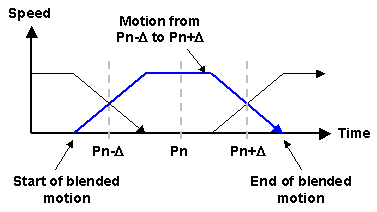
If you desire to trigger a signal when the robot reaches the end point of a motion, but that motion is blended with the subsequent motion, it is possible to trigger at approximately the correct position without regard to the details of the blending algorithms.  Specifically, if you wish to trigger when the robot reaches position Pn, create two intermediate positions that are equidistance before and after Pn (Pn minus a small delta and Pn plus a small delta).  Then rather than moving to Pn, move to Pn minus the delta and then Pn plus the delta.  If you set the trigger to occur 50% of the way through the motion between these two intermediate positions, the signal will trigger when the robot is approximately at Pn. See .

If a motion terminates in the standard manner, the digital output signal or thread event is guaranteed to be asserted at some point during the motion.  However, if an error or RapidDecel function prematurely terminates a motion, the trigger may not be asserted.

Examples

Public Sub MAIN
Dim Evt_Thd As New Thread("Bckgnd_thread")
Dim pf1 As New Profile ' Use default accel/decel
Evt_Thd.Start ' Start background thread
Robot.Attached = 1 ' Get control of robot #1
Signal.DIO(20001) = 0 ' Turn off signal
Move.Trigger(0, 20, 20001) ' Turn on 20% into motion
Move.Trigger(1001, 10, Evt_Thd, &H10)' Trigger event 90% into motion
Move.Rel(Location.XYZValue(10), pf1) ' Move 10 mm in tool coordinates
Robot.Attached = 0 ' Release control of robot
End Sub

Public Sub
Bckgnd_thread()
Thread.WaitEvent(&H10, -1) ' Wait for trigger
Signal.DIO(20001) = 0 ' Turn off signal
Console.WriteLine("Thread triggered")
End Sub

See Also

Move Class