Open topic with navigation
Current Loop Tuning Procedure
The lowest level of motor control implements a digital feedback loop that ensures that each amplifier generates the desired current in response to a torque command from the servo code. This motor current feedback loop must be tuned for a given type of motor. Fortunately, this tuning is very simple (easier than tuning a PID loop) and the tuning is indifferent to the load placed on the motor or the operating speed of the motor. In fact, in some instances, it is more convenient to current loop tune a motor when it is sitting on a bench before it is installed in a mechanism.
The purpose of the current loop tuning is to ensure that the current flowing through the motor rises quickly, with minimum overshoot, in response to a current command. The rise time and current magnitude are a function of the electrical properties of the motor (e.g. its inductance and resistance) and not of the mechanical properties of the total drive system (e.g. motor payload and motor speed). So, once the current loop tuning parameters are established for a type of motor, the same settings can be applied to all motors of the same type independently of how they are being used.
If the motor current loop tuning parameters are set properly, the current and torque generated by a motor will rise quickly in response to a motion command. If the current loop tuning is poor, the motor can react sluggishly or the current command can significantly over-shoot the desired command and cause amplifier faults when a motor is rapidly accelerated or driven at high speed.
For each amplifier, a single set of current tuning parameters are applied to two independent current control loops, Iq and Id. For standard brushless motors, the Iq loop corresponds to the torque output of the motor. The Id loop is provided for other types of motors and typically has a set point command of 0 amps.
The current loop tuning is specified by two values in the Parameter Database as described in the following table.
| Parameter Database ID
|
Parameter Name
|
Description
|
|
10656
|
Current loop proportional gain, Kp
|
For both the Iq and Id control loops, the error between the commanded current and the actual current (as determined from the current feedback) is multiplied times the "Current loop proportional gain" to correct the output of the amplifier. This value is normally specific to a motor and independent of the axis in which the motor is utilized. Typical values for this parameter range from .004 to 0.04 but values outside of this range are also possible.
|
|
10657
|
Current loop damping gain, Kv
|
For both the Iq and Id control loops, the rate of change in the error between the commanded current and the actual current (as determined from the current feedback) is multiplied times the "Current loop damping gain" to correct the output of the amplifier. If this gain is increased in magnitude, the current loop becomes more stable but at the expense of having the current loop more slowly react to changes in the current command. This value is normally specific to a motor and independent of the axis in which the motor is utilized. Typical values for this parameter range from .004 to 0.4 but values outside of this range are also possible.
|
To facilitate tuning the current loop for a type of motor, the controller web interface includes a special panel. This panel permits a single phase of a motor to be driven with a square wave current command at a specified % of its maximum permitted motor current. During this test, the actual current verses the commanded current is automatically captured by the Datalogger. After the test, the results can be plotted by pressing a button.
When current loop tuning a motor, it is highly recommended that the output shaft of the motor not move during the test. If the motor moves, the motor commutation compensation will generate a sinusoidal output to each motor phase. This variation in the current amplitude can mask the motor's true response to a current command. If the motor is not subject to gravity loading, the rotor and stator of the motor can be driven to align a single phase using the "twang" command. During subsequent executions of the twang command, the motor will not move since the same phase of the rotor and stator will continue to be forced into alignment. If the motor is subject to gravity loading or some other bias force, after the first twang command is executed, the motor should be locked into position using its brake or some other physical device to ensure that the motor remains stationary during the tuning process.
To tune the current loop for a type of motor, the following procedure should be executed.
- Open the controller's web interface and access the Current Loop Tuning panel.
This is normally done by selecting Setup > Hardware tuning and diagnostics > Current Loop Tuning. You should see the following window.
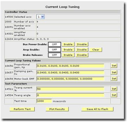
- Select a motor and enable power.
At the top of the tuning panel select the desired motor to test. Enable the ‘Bus Power’ and then the ‘Amp Enable’. Enabling the bus power turns on the high voltage power supply and supplies power to the amplifiers. Enabling the amplifiers provides power to the motors. Thus, the order of turning on the ‘Bus Power’ and ‘Amp Enable’ is important to avoid amplifier faults.
It is important to turn off ‘Amp Enable’ and ‘Bus Power’ before leaving this page and or changing to another axis for testing.
- Align a motor phase and perform the motor current test.
Set the ‘Twang Current’ (14511) to a reasonable value. Start small (10%) and work up to 100% after each test.
Click on the ‘Perform Test’ button. This operation will energize the motor phases to the specified electrical angle (set by ‘Twang Angle DataID 14503’). The electrical angle dictates which of the motor phases will be energized and what portion of the power they will receive. Typically, a value of 0 degrees for the electrical angle is acceptable.
It is important that the motor not move for accurate tuning. If the motor does move when clicking on the ‘Perform Test’ button, try repeating the operation. This first type you performed a test, the system will be pulling the motor phases into alignment.
If the motor moves again, then it may be required to physically clamp the motor into place by setting its brake or using a mechanical clamp on the motor output shaft.
If you attempt to tune allowing the motor to move, the resulting plotted data could show inaccurate results.
- Plot test results
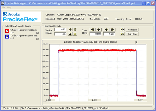
Click ‘Plot Results’. This operation will retrieve the data from the Datalogger. In this case, the stored data will represent the results from the last current loop test.
If you have installed the Guidance Development Suite, the Datalogger file can automatically be viewed using the Guidance Datalogger Viewer. If you have not installed GDS, the results will be retrieved by the web interface and can be viewed in any application capable of displaying a comma delimited text file.
The following picture illustrates a current loop plot where the current loop has been tuned. In the next section, pictures are presented that illustrate poorly tuned motors. In this correctly tuned motor, notice that the ‘12659 current feedback’ (red) follows the ‘12664 current command’ (blue) very closely.
- Iteratively determine the current loop feedback constants.
Repeat steps 3 and 4 while adjusting the Kp and Kv values until you achieve a reasonable plot.
Every motor type may have different tuning values. However, motors of the same type should use the same current tuning values.