Selected kinematic modules support Dynamic Feedforward compensation (DFF). This technique utilizes a dynamic model of the robot to generate feedforward terms that can significantly reduce the tracking errors and improve the gravity balance for some mechanisms. These feedforward terms compensate for the effects of inertial acceleration, centripetal, Coriolis and other coupled forces, and gravity loading. This compensation is designed to counteract dynamically coupled reactions where one axis will experience a disturbance force or torque that is generated by the movement or mass of another axis.
For example, for a SCARA robot, if only the outer link is rotated quickly, coupled inertial, centripetal and Coriolis forces will generate a torque that will attempt to rotate the inner link. This typically results in the inner link exhibiting a momentary position error even though it is not being moved. In this case, Dynamic Feedforward compensation will predict the coupled torque and will generate a feedforward command to counteract this disturbance. This will eliminate or significantly reduce any position error of the inner link.
DFF is most beneficial for axes with 1:1 or small gear ratios (such as direct drive or belt driven axes) or for axes that are subject to significant variable gravity loading. This is due to the fact that axes with high gear ratios (50-100 to 1) tend to mask out link inertial and coupled torques. For such axes, the major dynamic factors are the friction of the gear train and the inertia of the motor rotor and the gear train on the side of the motor.
DFF operates by continuously sampling the position, speed, and acceleration of each axis, and combining this information with the dynamic model of the robot to produce an estimated feedforward force or torque for most axes. These feedforward values are converted to a motor current and added to the standard axes PID loops. As with kinematic equations, the dynamic model utilized by the DFF facility is designed for a specific robot geometry. Therefore, only selected kinematic modules include support for DFF and the terms in the dynamic model are specific to the robot’s geometry.
The DFF equations are evaluated at the Trajectory Update Rate, which is typically once each 1 to 4 msec. Tests to date indicate that enabling DFF only consumes approximately 1-2% of the master controller’s CPU time.
The following Parameter Database values are utilized for setting up, operating and monitoring DFF.
| Parameter Database ID | Parameter Name | Description |
|---|---|---|
|
16066 |
Dynamic feedforward enable |
If a kinematic module supports Dynamic Feedforward (DFF) and this parameter is TRUE when the system is restarted, DFF compensation will be enabled until the controller is powered down. |
|
16067 |
Dynamic feedforward mass, kg |
These parameters, along with the kinematic model, the "Dynamic feedforward motor/gear inertia" (DataID 16072), and the "Kinematic dimensional constants" (DataID 16050) define the physical constants necessary for computing the Dynamic Feedforward compensation (DFF). |
|
16068 |
Dynamic feedforward COM l1, mm |
|
|
16069 |
Dynamic feedforward COM l2, mm |
|
|
16070 |
Dynamic feedforward rated torque, N-m |
Once the Dynamic feedforward is computed for axes (in N-m or N), the torques or forces must be converted to motor current commands. The values of this DataID are used for this conversion. The "Dynamic feedforward rated torque" is the torque or force that is generated at an axis (not a motor) when a motor is supplied with the current defined by the "RMS rated motor current, A(rms)" (DataID 10611). |
|
16071 |
Dynamic feedforward default %payload |
When the system is restarted, this parameter sets the value of Robot.Payload between 0 and 100%. This robot property specifies the current payload of the robot as a percentage of the maximum payload, which is defined by the "Dynamic feedforward mass" (DataID 16067). Once the system is running, a GPL program can change this default value by setting Robot.Payload to a new value. |
|
16072 |
Dynamic feedforward motor/gear inertia, kg-mm^2 |
For each axis, this parameter specifies the inertia of each axis' motor and gear box as seen at the axis (after being compensation for the axis' gear ratios). These values together with the Dynamic Feedforward parameters defined by DataIDs 16067-16069, the robot's kinematic model, and the "Kinematic dimensional constants" (DataID 16050) define the physical constants necessary for computing the Dynamic Feedforward compensation (DFF). |
|
12337 |
Dynamic feedforward torque, tcnt |
For kinematic modules that generate Dynamic Feedforward torques, this parameter indicates the DFF torque command that was received from the Trajectory Generator and was added to the position loop compensator, in tcnts. The "Feedforward torque" (DataID 12330) does not include DFF. DFF is added to DataID 12330 before the combined value goes through the "Feedforward SPR filter" (DataID 10328) and the "Feedforward torque rate limit" (DataID 10348). |
|
12406 |
Dynamic feedforward torque command, tcnt |
For kinematic modules that generate Dynamic Feedforward torques, this parameter indicates the DFF torque command that was received from the Trajectory Generator, in tcnts. Unlike the "Dynamic feedforward torque" (DataID 12337) that is only valid when a servo is in position control mode, this value is valid in any mode including torque control mode. It displays the DFF value whether or not this value is added to the motor output. |
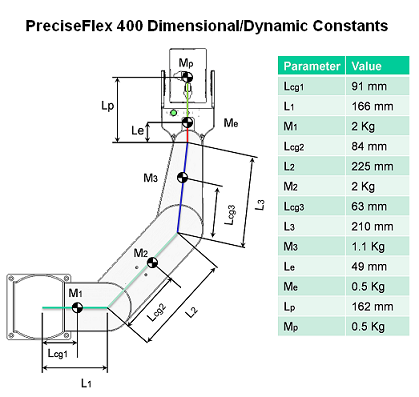
As an example of how to initialize the DFF parameters, the following illustrates how the DFF parameters are defined for the PreciseFlex™ 400 robot. This robot utilizes the PRRR kinematic module. The picture below illustrates the dimensional and dynamic constants for this robot. Please note that the Ln parameters in the drawing are not the same as the DFF COM L1 and L2 values.
The following table provides the necessary information for the motor drives.
| Motor | Size (W) |
Rated Torque (N-m) at Rated Current | Gear Ratio or N-m to N factor |
|---|---|---|---|
|
1 |
200 |
0.64 |
160 |
|
2 |
100 |
0.318 |
3.75 : 1 |
|
3 |
100 |
0.318 |
4.72 : 1 |
|
4 |
30 |
0.095 |
3.54 : 1 |
Please refer to the definitions for the Mn, L1n and L2n terms that are provided in the documentation for the PRRR kinematic module. Based upon the information provided for the kinematic module and the data above, the following values are set into the DFF Parameter Database values for this robot.
| Parameter Database ID | Parameter Name | Values |
|---|---|---|
|
16066 |
Dynamic feedforward enable |
1 |
|
16067 |
Dynamic feedforward mass, kg |
2, 2, 1.1, 0.5, 0.5 |
|
16068 |
Dynamic feedforward COM l1, mm |
0, 84, 63, 49, 162 |
|
16069 |
Dynamic feedforward COM l2, mm |
0, 0, 0, 0, 0 |
|
16070 |
Dynamic feedforward rated torque, N-m |
102.4, 1.1925, 1.5, 0.336 |
|
16071 |
Dynamic feedforward default %payload |
Any value from 0 to 100 |
|
16072 |
Dynamic feedforward motor/gear inertia, kg-mm^2 |
Not currently used |
Please note, that the 5th values for DataID's 16067 and 16068 represent the maximum payload for the robot and its position relative to the center of rotation of axis 4. The actual payload mass utilized in the DFF calculations will be the product of the maximum payload times the Robot.Payload percentage (0-100%). This permits the payload mass to be modified by a GPL program as the robot picks up and places objects.
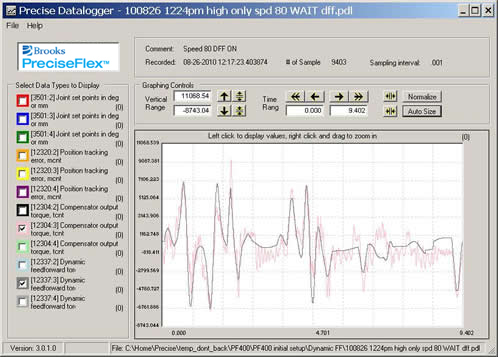
For this robot, the following datalog illustrates how well the torque feedforward command computed by the DFF matches the actual torque required for a motion. The pink line displays the total command output by the servo compensator loop for axis 3. The dark gray line illustrates the feedforward torque command generated by the DFF software. For other mechanisms, the accuracy of the DFF calculations (and their benefit) will vary and be a function of many factors including the motor gear ratios, the system friction, etc. For this robot, the DFF compensation was able to reduce the robot tracking error by more than a factor of 2 for many motions.