For most mechanisms, there is a one-to-one correspondence between motors and axes (“joints”). For example, in a typical XYZ Cartesian mechanism, there is a single motor that is responsible for driving the mechanism along its X-axis, a second motor for Y motion and a third motor solely responsible for Z travel. Likewise, in a SCARA robot, the first motor is solely responsible for rotating the waist of the robot about the Z-axis. In these cases, a single scaling factor defines the conversion from a joint position (in millimeters or degrees) to a motor encoder count:
where
motori is the motor position in encoder counts
sfi is the conversion scale factor from jointi to motori
jointi is the axis position in millimeters or degrees
In other mechanisms, two or more motors combine to determine the motion of an axis, or two or more axes combine to determine the motion of a motor. In some cases, such as wrists axes driven by differential gearing, this “coupling” is by design. In other cases, the coupling is due to imperfect manufacturing tolerances, such as the interaction of the X and Y motors in a Cartesian mechanism where the X and Y-axes are not perfectly perpendicular.
Scale Factor Coupling Matrices
To represent the mechanical coupling between multiple motors and multiple axes, selected kinematic modules utilize a matrix of scale factors to perform the conversion between joint coordinates and motor encoder counts in place of the simple scalar scaling factors. For example, to account for coupling between two axes, the 2-by-2 coupling matrix is as follows:
![]()
where
csf1 defines the change in motor1 due to joint1
csf2 defines the change in motor1 due to joint2
csf3 defines the change in motor2 due to joint1
csf4 defines the change in motor2 due to joint2
If this matrix is used to represent un-coupled joints and motors, csf1 is the conversion factor from joint1 to motor1 and is equivalent to sf1, csf4 is the conversion factor from joint2 to motor2 and is equivalent to sf2, and csf2 and csf3 are zero. This is referred to as a "diagonal" matrix since only the diagonal terms are non-zero.
By extension, if three joints and motors interact, the 3-by-3 coupling matrix is as follows:
where
csf1 defines the change in motor1 due to joint1
csf2 defines the change in motor1 due to joint2
csf3 defines the change in motor1 due to joint3
csf4 defines the change in motor2 due to joint1
etc.
Lastly, if four joints and motors interact, the 4-by-4 coupling matrix is as follows:
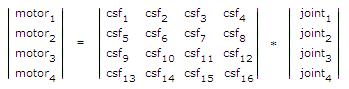
where
csf1 defines the change in motor1 due to joint1
csf2 defines the change in motor1 due to joint2
csf3 defines the change in motor1 due to joint3
csf4 defines the change in motor1 due to joint4
csf5 defines the change in motor2 due to joint1
etc.
Since the controller must be able to convert from motor encoder counts to joint angles to read the instantaneous position of the robot, the system automatically computes the inverse coupling matrix for the 2-by-2, 3-by-3, and 4-by-4 matrices.
Scale Factor Storage in the Parameter Database
Independent of whether scaling factors are simple scalars or part of a coupling matrix, the values for all scaling factors are stored in the following Parameter Database element.
| Parameter Database ID | Parameter Name | Description |
|---|---|---|
|
2300 |
Joint to motor scale factors |
This is an array of 20 double precision scaling factors that convert from joint positions (in millimeters or degrees) to motor encoder positions (in encoder counts). |
For example, for a four axis robot without coupling, the first four values in this array contain the conversion factors from jointi to motori as follows:
sf1, sf2, sf3, sf4, 0, 0, ...
As another example, for the Enhanced XYZTheta module with all four axes configured, the coupling for the first three axes is represented by a 3-by-3 matrix and the Theta has a single scalar scaling factor. The values of DataID will be as follows:
csf1, csf2, csf3, csf4, csf5, csf6, csf7, csf8, csf9, sf4, 0, ...
In general, the scaling factor array stored in the Parameter Database can contain any combination of single scaling factors and coupling matrices. The contents of this array is dictated by the robot module in use.