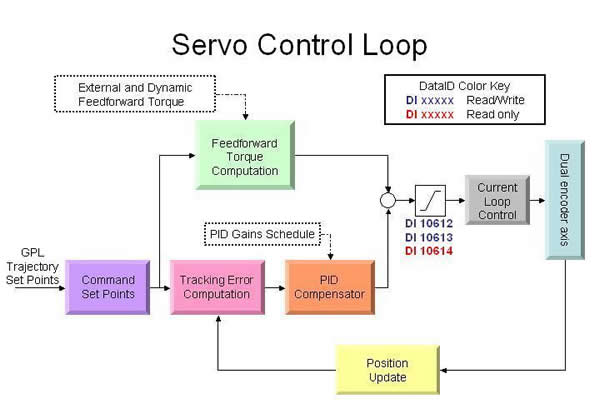
The following block diagrams present a simplified over-view of the operation of the Servo Motor Control subsystem. This software accepts set-point commands from the GPL trajectory generator, implements the PID loop to compute the required motor torque to follow the trajectory, and sends the torque command to the motor current feedback loop.
Each diagram contains the DataID numbers of the primary Parameter Database values that control the operation of the Servo Code and the DataID values that can be used to datalog and monitor the operation of this software.
These diagrams represent the most common operation of the Servo Code including dual-loop encoder feedback and optional input from an external trajectory generation source. However, these diagrams have been simplified and should not be considered an accurate representation of the operation of the software. Many details and parameters have been eliminated for the sake of simplicity and clarity.
Referenced DataIDs: 10612, 10613, 10614
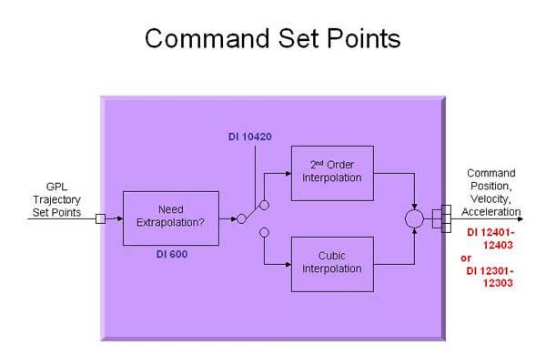
Referenced DataIDs: 600, 10420, 12301, 12302, 12303, 12401, 12402, 12403
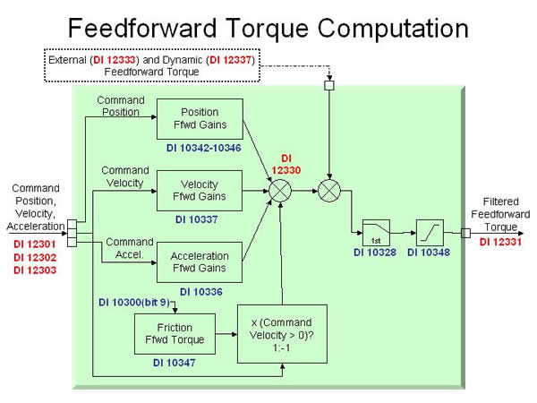
Referenced DataIDs: 10300, 10328, 10336, 10337, 10342, 10343, 10344, 10345, 10346, 10347, 10348, 12301, 12302, 12303, 12330, 12331, 12333, 12337
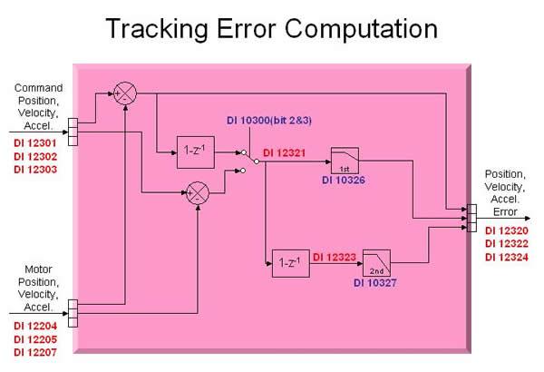
Referenced DataIDs: 10300, 10326, 10327, 12204, 12205, 12207, 12301, 12302, 12303, 12320, 12321, 12322, 12323, 12324
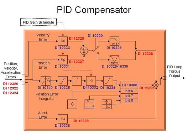
Referenced DataIDs: 10300, 10329, 10330, 10331, 10332, 10333, 10334, 10335, 10338, 10340, 12320, 12322, 12324, 12325, 12326, 12327, 12328, 12329
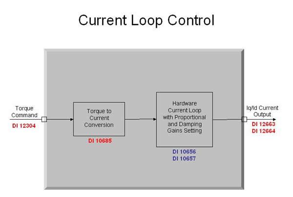
Referenced DataIDs: 10656, 10657, 10685, 12304, 12663, 12664
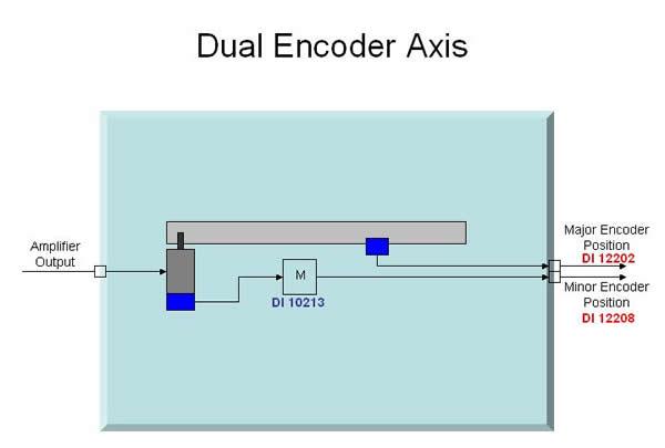
Referenced DataIDs: 10213, 12202, 12208
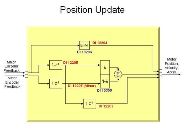
Referenced DataIDs: 10206, 10305, 12204, 12205, 12207