Guidance Controllers can automatically monitor the temperatures of motors and generate an error if any temperature exceeds its specified limit. To employ this feature, the motors must be equipped with analog temperature sensors and the controller must be equipped with General Purpose Analog Inputs. Different controller models are available with 0, 2 or 4 such analog inputs.
This function has been designed to operate with Philips KTY84/130 silicon temperature sensors or with any Positive Temperature Coefficient (PTC) thermistor device.
The KTY84/130 sensor is a device whose resistance changes almost linearly over its operating range. This permits the actual temperature of the motor to be read at any time to determine if the motor is close to its thermal limit. When this sensor is employed, the temperature trip point must be set in software to the maximum permitted value that is specified by the motor manufacturer.
In contrast, PTC sensors operate almost like binary switches and provide relatively little information on the instantaneous temperature of the motor. The resistance of these devices is fairly constant until the Nominal Response Temperature (NRT) is reached, at which point the resistance changes abruptly. When a motor manufacturer uses these sensors, they select a device with a NRT that is appropriate for the motor. Also, for multi-phase motors, up to 3 PTC sensors can be wired in series within the motor and can be properly handled by the Guidance Controller.
To configure motor temperature sensing, either the maximum operating temperature must be specified for motors with KTY84/130 sensors, or the number of PTC devices that are in series in a motor must be defined.
Once configured, if any motor exceeds its maximum temperature, motor power is disabled and the error code -1610 "Controller overheating" is generated.
Motor temperature monitoring is enabled by setting parameter "Max motor temperature" (DataID 10110) to a non-zero value. For KTY84/130 sensors, the actual temperature can be read from the parameter "Motor temperature" (DataID 12110).
| Parameter Database ID | Parameter Name | Description |
|---|---|---|
|
10110 |
Max motor temperature |
If zero, motor
temperature checking is disabled. |
|
10111 |
Warning motor temperature |
|
|
12110 |
Motor temperature |
If motor temperature
sensing is enabled, as indicated by a non-zero "Max motor
temperature" (DataID 10110) value, this parameter indicates
the current motor temperature. |
Analog Input Channel Mapping
If motor temperature sensing is enabled, the first General Purpose Analog Input channel samples the temperature sensor for the motor that is connected to amplifier #1. Likewise, the 2nd, 3rd, and 4th analog inputs are assigned to the 2nd, 3rd, and 4th amplifiers respectively. The correspondence between an analog input channel and a robot axis is dictated by the parameter "Amplifier hardware channel number" (DataID 10028). For example, if the first amplifier channel is assigned to the 2nd axis of a robot, the first analog input channel will provide the temperature for the motor for the robot's second axis.
Sensor Interfacing
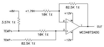
To connect a KTY84/130 temperature sensor you must provide an interface circuit that converts the resistance reading of the sensor into a voltage level. The table below shows the expected analog channel input voltage values for a range of temperatures:
| KTY84 / 130 | |
|---|---|
| Temp C | Voltage |
|
0 |
-6.53 |
|
10 |
-5.99 |
|
20 |
-5.41 |
|
30 |
-4.82 |
|
40 |
-4.24 |
|
50 |
-3.60 |
|
60 |
-2.98 |
|
70 |
-2.35 |
|
80 |
-1.69 |
|
90 |
-1.04 |
|
100 |
-0.36 |
|
110 |
0.31 |
|
120 |
0.99 |
|
130 |
1.66 |
|
140 |
2.33 |
|
150 |
3.02 |
|
160 |
3.70 |
|
170 |
4.37 |
|
180 |
5.05 |
|
190 |
5.72 |
|
200 |
6.39 |
To connect PTC sensors, you must provide an interface circuit that generates voltage levels from the sensor as show in the table below. Because the analog input is limited to +/- 10V, the threshold accuracy is reduced when using 2 or 3 sensors in series.
| PTC Sensor Voltage | ||
|---|---|---|
| # Sensors | Resistance (ohms) | Voltage |
|
1 |
< 250 |
< -9.7 V |
|
1 |
> 1330 |
> 3.0 V |
|
2 |
< 500 |
< -6.5 V |
|
2 |
> 2660 |
> 10 V |
|
3 |
< 750 |
< 3.2 V |
|
3 |
> 3990 |
> 10 V |
This drawing below illustrates an example interface circuit that can be used for both the Philips KTY40/130 sensor and a typical PTC sensor.