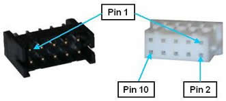
(REQUIRES IO DAUGHTER BOARD) The remote front panel interface includes a serial port for connecting to a Manual Control Pendant (MCP) and redundant E-Stop inputs for receiving an hardware E-Stop signal. These signals are all that is needed to implement a remote front panel that is proper for a low voltage, low power control system. These signals are provided on a single 10-pin JST S10B-PHDSS(LF)(SN) connector that mates with a JST PHDR-10VS plug.
Figure 62-74: Ten-pin JST S10B-PHDSS(LF)(SN) Connector and JST PHDR-10VS Plug
If a Manual Control Pendant is not connected to the RS-232 port, this serial interface can be accessed via a GPL procedure as device /dev/com2 for general communications purposes.
If a remote front panel, MCP with E-Stop or a E-Stop button is not interfaced to this connector, the following pins on the front panel connector must be jumpered in order for the controller to operate properly. (The controller is shipped with these jumpers installed.)
1-2, 3-4
The pin out for the Remote Front Panel Connector is described in Table 62-61.
| Pin | Description |
|---|---|
|
1 |
ESTOP_L 1 (If no front panel or E-Stop not asserted, connect to pin 2). An input signal that is low or open indicates that a hardware E-Stop condition has been asserted by some source. Set high if no E-Stop condition is asserted. The controller hardware will not permit motor power to be enabled when an E-Stop condition exists. |
|
2 |
Force ESTOP_L. Output signal that, when low, indicates that the Remote Front Panel should force ESTOP_L 1 and ESTOP_L 2 to be asserted (low). The System Software toggles this signal low at startup to verify that the ESTOP_L 1 and ESTOP_L 2 are properly working. The System Software also uses this as a means for asserting a hardware E-Stop condition during normal operation. This signal is normally held high. |
|
3 |
ESTOP_L 2 (If no front panel or E-Stop not asserted, connect to pin 4). Redundant ESTOP input signal. |
|
4 |
Force ESTOP_L. Redundant Force ESTOP_L output signal. |
|
5 |
MCP RXD - controller receive data. |
|
6 |
MCP TXD - controller transmit data |
|
7 |
24VDC output |
|
8 |
GND |
|
9 |
5 VDC output |
|
10 |
GND |
|
User Plug Part No |
JST PHDR-10VS. For this plug, use JST SPHD-002T-P0.5 pins. |