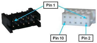
(REQUIRES IO DAUGHTER BOARD) This optional multi-function interface provides a general purpose RS-485 serial port and redundant output signals that can control turning on and off the external motor power supply. These signals are provided on a single 10-pin JST S10B-PHDSS(LF)(SN) connector that mates with a JST PHDR-10VS plug.
Figure 62-76: Ten-pin JST S10B-PHDSS(LF)(SN) Connector and JST PHDR-10VS Plug
The motor power enable signals are configured as a redundant pair of sinking signals. These should be wired to a pair of relays that are connected in series to enable and disable the motor power supply. Normally, 5 to 24VDC is applied to this control circuit. The external motor power supply should be turned on when the controller's logic switches the "power enable " signals to ground. These signals are automatically opened when an E-Stop or other condition occurs that requires that the amplifiers be shutdown. See the Connecting Power and Enabling Motor Power section of this manual for general information concerning enabling motor power.
The pin out for the RS-485 / Motor Power Enable Connector is described in Table 62-63.
| Pin | Description |
|---|---|
|
1 |
Motor power enable. Switched to ground when power is being enabled. Capable of sinking 2 A at 24VDC. |
|
2 |
Motor power enable (Redundant signal). Provided to comply with safety standards. |
|
3 |
RS-485+ |
|
4 |
RS-485- |
|
5 |
Reserved |
|
6 |
Reserved |
|
7 |
24VDC output |
|
8 |
GND |
|
9 |
5VDC output |
|
10 |
GND |
|
User Plug Part No |
JST PHDR-10VS. For this plug, use JST SPHD-002T-P0.5 pins. |