The HVCPU provides twelve general-purpose optically isolated digital input signals that are accessed in a single IDC connector. This type of connector permits these signals to be easily interfaced to other devices.
These inputs can be configured as either "sinking" or "sourcing" in groups of four (4) signals. If an input signal is configured as "sinking," the external equipment must provide a 5VDC to 24VDC voltage to indicate a logical high value or no voltage for a logical low. This configuration is compatible with "sourcing" (PNP) sensors.
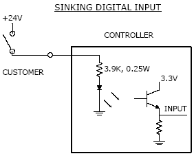
Figure 17-30: DIO Sinking Input
If an input signal is configured as "sourcing," the external equipment must pull the signal input pin to ground to indicate a logical high and must let the line float high to 24VDC to signal a logical low value. This configuration is compatible with "sinking" (NPN) sensors.
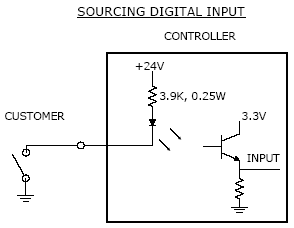
Figure 17-31: DIO Sourcing Input
In place of the hardware jumpers that were employed in earlier Guidance controllers to configure the sinking /sourcing mode of operation, in the G6000 controllers these settings are changed via software parameters. This method is more convenient especially if the controller is embedded in a robot. Table 17-12 lists the parameter controls of the digital input's modes of operation.
| Parameter Database ID | Parameter Name | Default Value | Description |
|---|---|---|---|
|
531 |
DIN sink mode 1-4, 5-8, 9-12 |
0 (Sourcing) |
For newer controllers that support software DIO configuration, this parameter sets and displays whether local digital input signals operate in sinking or sourcing mode. The input signals are set in groups of four. A group of inputs are sinking if their corresponding element is 1, otherwise a value of 0 indicates sourcing. By default, all local inputs (GPL signals 10001-10012) are set to sourcing. |
To modify the sinking/sourcing mode of operation for a group of digital inputs, use a browser to open the controller's web interface and access the following page: Setup ® Parameter Database ®Controller ® System DIO. To save modifications, click Set new valuesfollowed by Save All to Flash.
NOTE: Whenever saving to flash, to turn off the controller, wait 10 seconds after the "Flash Busy" indicator disappears to ensure the flash disk is not corrupted.
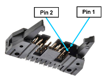
The pin out for the Digital Input Connector and the corresponding GPL signal numbers are described in Table 17-13.
| Pin | GPL Signal Number | Description |
|---|---|---|
|
1 |
|
24VDC |
|
2 |
|
GND |
|
3 |
10001 |
Digital Input 1 |
|
4 |
10002 |
Digital Input 2 |
|
5 |
10003 |
Digital Input 3 |
|
6 |
10004 |
Digital Input 4 |
|
7 |
10005 |
Digital Input 5 |
|
8 |
10006 |
Digital Input 6 |
|
9 |
10007 |
Digital Input 7 |
|
10 |
10008 |
Digital Input 8 |
|
11 |
10009 |
Digital Input 9 |
|
12 |
10010 |
Digital Input 10 |
|
13 |
10011 |
Digital Input 11 |
|
14 |
10012 |
Digital Input 12 |
|
15 |
|
24VDC |
|
16 |
|
GND |
|
User Plug Part No |
|
Amp 746285-3 or Molex 22-55-2161 or Molex 90142-0016. For the Molex plugs, use Molex pins 16-02-0103 and Molex crimp tool 63811-1000. |