There are four 16-pin encoder connectors on the PreciseFlex G6000s top HVCPU board. Two of these connectors are mounted on each end of the HVCPU. Each of these connectors provides the signals necessary to interface to one or possibly two encoders. The numbering of these connectors defines how the software references these interfaces and the numbering is different in the 4-axis and the 6-axis versions of the controller.
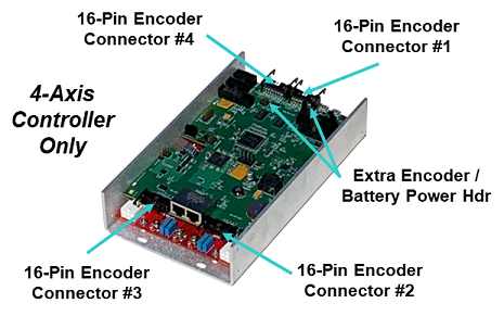
For backwards compatibility with the previous generation of 4-axis Guidance G2400C controllers, the 4-axis version of the PreciseFlex G6000 has its encoders interfaces numbered as shown in Figure 17-43.
Figure 17-42: Encoder Connectors
In addition to the encoder interface signals, each encoder connector contains a pair of pins that are routed though the controller to an optional external encoder battery. This battery can provide backup power to absolute encoders when the controller is powered down. Each encoder connector also includes multiple ground pins and a single pin that provides 5VDC to power an encoder.
As a wiring convenience, when either or both of the two connectors at the far end of the controller are interfaced to two absolute encoders, the "Extra Encoder / Battery Power Headers" provide additional battery and 5VDC encoder power pins that eliminate the need to double crimp two wires to the standard pins in the encoder connectors. These headers reconfigure pins in the encoder connectors that are usually designated as extra grounds to provide additional external battery and 5VDC power instead. See below for more information on these headers.
In the 6-axis version of the PreciseFlex G6000 (as shown in Figure 17-43), the motor amplifiers and their connectors are re-arranged to permit optimal heat dissipation given the number of high voltage amplifiers that are provided in a very small footprint. Since the cables for motors and their corresponding encoders are typically bundled together, the encoder channels are renumbered to simplify wiring to the controller.
The encoder connectors are configured so that a variety of incremental or absolute encoders can be connected to the controller. Pins 2, 3, 5, 6, 8, and 9 are allocated to the first encoder and are compatible with standard 5 VDC digital signals. Absolute encoders are interfaced via these same signal pins. (See "Third Party Equipment Overview" on page 1 for information on connecting supported absolute encoders.) Either single-ended or differential encoder signals can be connected to the primary encoder interface. (Absolute encoder interfaces may require a special "Enhanced Encoders" license due to special hardware and/or firmware requirements.)
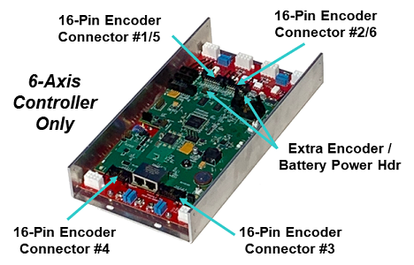
Figure 17-43: Encoder Connectors
In addition to the primary encoder interface, there are three digital inputs available in each encoder connector. These can be configured for hall-effect sensors or two over-travel sensors plus a homing sensor. When configured for these functions, they should be treated as standard 5VDC sourcing digital inputs connections. Alternatively, these three digital signals can interface to a second, single-ended encoder. This single-ended encoder can be used independently of the primary encoder or the two encoders can be used together to implement dual encoder loop servo control of an axis of motion.
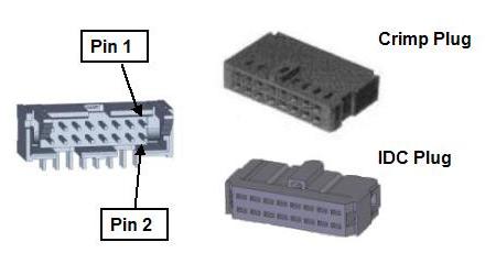
Figure 17-44: Encoder Plugs and Connectors
Table 17-22 defines the encoder connector pin outs. The second column should be used when the three digital inputs are configured for hall-effect sensors or over-travel switches and a homing sensor. The third column describes the pin outs when a second, single-ended encoder is utilized.
| Pin | 3 Digital Inputs (5VDC) |
2nd Encoder (5VDC) |
|---|---|---|
|
1 |
Gnd |
|
|
2 |
Encoder 1 A+ |
|
|
3 |
Encoder 1 A- |
|
|
4 |
5VDC provided to power encoders. The sum of the current drawn from all four encoder connectors is limited to 1 amp. |
|
|
5 |
Encoder 1 B+ |
|
|
6 |
Encoder 1 B- |
|
|
7 |
Gnd |
|
|
8 |
Encoder 1 Z+ |
|
|
9 |
Encoder 1 Z- |
|
|
10 |
Gnd |
|
|
11 |
Digital Input #1 |
Encoder 2 A+ |
|
12 |
Normally Gnd (Reserved for Abs Encoder Battery Gnd). Alternately, for the JP7 and JP8 encoder connectors, this pin can provide Abs Encoder Battery Pwr if jumpers are changed on the "Extra Encoder / Battery Power Headers" J44 and J43 respectively. |
|
|
13 |
Digital Input #2 |
Encoder 2 B+ |
|
14 |
Vcc (Reserved for Abs Encoder Battery Pwr) |
|
|
15 |
Digital Input #3 |
Encoder 2 Z+ |
|
16 |
Normally Gnd. Alternately, for the JP7 and JP8 encoder connectors, this pin can provide 5VDC if jumpers are changed on the "Extra Encoder / Battery Power Headers" J22 and J21 respectively. |
|
|
Board Header |
Amp 104315-03-3-o-s |
|
|
Crimp Plugs |
Amp 102387-3 or Molex 90142-0016. For the Amp plug, use Amp pins 102128-1 and AMP crimp tool 91517-1. For the Molex plug, use Molex pins 16-02-0103 and Molex crimp tool 63811-1000. |
|
|
Alternate IDC Plug |
Amp 746285-3 |
|
As shipped from the factory, the JP7 and JP8 encoder connectors only provide one 5VDC power pin and one encoder battery power pin. If the controller is being interfaced to six absolute encoders, two encoders must be wired to each of these encoder connectors. To eliminate the need to double crimp to the encoder and battery power pins, the "Extra Encoder / Batter Power Headers" permit spare ground pins in JP7 and JP8 to be reconfigured to extra encoder and battery pins.
The "Extra Encoder / Battery Power Headers" consist of two groups of two three-post headers that are located close to the JP7/JP8 encoder connectors that they modify.

Figure 17-45: Jumper Posts
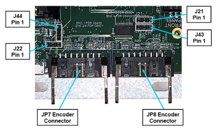
Figure 17-46: Encoder Connectors and Pins
The J43 header controls whether pin 12 of the JP8 encoder connector is connected to the encoder battery ground or the battery power source. The center post of the J43 header must be jumpered to either pin 1 or pin 3 as defined in Table 17-23. Likewise, the J44 header controls whether pin 12 of the JP7 encoder connector is connected to the battery ground or the battery power source. By default, pins 1 and 2 of J43 and J44 will be shorted with a shunt. Move the shunt to pins 2 and 3 if using 6 absolute encoders in a 6-axis controller configuration (G6600).
| Pin | Description |
|---|---|
|
1 |
Abs Encoder Battery Gnd |
|
2 |
JP7 or JP8 pin 12, jumper to pin 1 or 3 |
|
3 |
Abs Encoder Battery Pwr |
The J21 header controls whether pin 16 of the JP8 encoder connector is a ground or a 5VDC source. The center post of the J21 header must be jumpered to either pin 1 or pin 3 as defined in Table 17-24. Likewise, the J22 header controls whether pin 16 of the JP7 encoder connector is a ground or a 5VDC source. By default, pins 1 and 2 of J21 and J22 will be shorted with a shunt. Move the shunt to pins 2 and 3 if using six absolute encoders in a 6-axis controller configuration (G6600).
| Pin | Description |
|---|---|
|
1 |
Ground |
|
2 |
JP7 or JP8 pin 16, jumper to pin 1 or 3 |
|
3 |
5VDC encoder battery power |