The encoder connectors on the HVCPU board can each be cabled to a differential encoder and an optional single-ended encoder. If a single-end encoder is not interfaced, these pins can be configured for use with hall effect sensors or end-of-travel/home switches. Whenever possible, the differential encoder inputs should be used instead of the single-end encoder inputs to achieve greater noise immunity.
If only a single-end incremental quadrature encoder is connected using twisted pair wire, the low side of both ends of each twisted pair should be connected to ground, and the A-, B-, and Z- signals of the controller's differential encoder inputs should each be pulled to 5V through a 2K resistor. The A+, B+, and Z+ signals should be connected without any special modifications.
If several wires must be connected to a single pin, a larger crimp pin should be used.
NOTE: If crimp style plugs are utilized, ensure that the crimp pins are gold plated and designed for high compression forces. Using tin plated pins or those with low contact forces can result in intermittent signals if there is any movement of the cables.
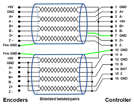
Especially for high frequency signals, such as those required for serial absolute encoders, it is critical that shielded twisted pair cable be used all the way from the encoder to the controller. Even a 300 mm unshielded non-twisted pair cable from the controller to a bulkhead connector can result in significant signal corruption.
Figure 17-19 illustrates how to interface differential and single-ended encoder input signals.