Open topic with navigation
System Diagram and Coordinate Systems
When the Guidance System D4 is interfaced to a DENSO SCARA mechanism, the major components of the system are as shown in Figure 66-43.
|
Consult the manuals that are provided with the DENSO SCARA mechanism for instructions on the proper installation, mounting and safeguarding of this device.
Electrical power should not be applied until the mechanism is in full compliance with these instructions.
|

|
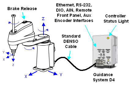
Figure 66-43: Standard DENSO 4-Axis Robot
The World and the Tool coordinate systems for the SCARA robot as well as the positive direction of rotation for each of the robot's rotary axes are shown in Figure 66-43. When the axes are in the positions indicated in this figure, they are all at their 0 positions. That is, when the axes positions are 0, the inner and outer links are aligned and pointing straight out in front of the base, the Z-axis is fully retracted (up), and the Theta is in the middle of its range of travel. When the third axis (the linear Z) moves down, the Z-axis position will increase and the end effector's World Z coordinate will decrease in value.
The linear Z-axis typically includes a fail-safe brake. This brake must be released to move the Z-axis up and down manually. DENSO typically provides a manual brake release button on the top of the mechanism's outer link. Clicking this button when the controller is powered on will release the Z-axis brake while the button is clicked. The user should carefully support the Z-axis when the brake release button is pushed, as the axis will fall due to gravity.
When the Guidance System D6 is interfaced to a DENSO 6-axis Articulated mechanism, the major components of the system are as shown in Figure 66-44.
|
Consult the manuals that are provided with the DENSO 6-axis mechanism for instructions on the proper installation, mounting and safeguarding of this device.
Electrical power should not be applied until the mechanism is in full compliance with these instructions.
|
|
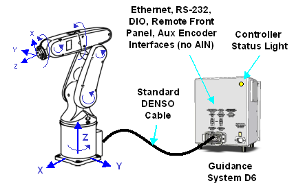
Figure 66-44: Standard DENSO 6-Axis Robot
The World and the Tool coordinate systems for this 6-axis robot as well as the positive direction of rotation for each of the robot's rotary axes are shown in Figure 66-44. When the axes are at their 0 positions (not illustrated), the first joint will be in the middle of its range of travel, the major axis of the inner and outer links will be vertical, the Tool Z-axis will be pointed in the positive World Z-direction, and the 4th axis and the Theta will be at the middle of their ranges of travel.
With regard to the general capabilities of both the D4 and D6, the system is compatible with a standard DENSO mechanism and can connect to the mechanism's motors and encoders utilizing an off-the-shelf robot cable provided by DENSO Robotics.
In addition to the motion interface, the Guidance System includes extensive communication interfaces:
- Two 10/100 Mbps Ethernet ports, a RS-232 serial interface
- Twelve digital input and eight digital output signal channels
- An interface for a remote front panel
- An additional eight digital input and eight digital output channels that are typically used for gripper control signals.
Optional integrated hardware is available that provides two or four analog inputs (not available on the D6), auxiliary encoder interfaces that can be used for conveyor belt encoders, and DC power for a camera and its light source.
An Ethernet port can be connected to a PC to enable access to the web-based GUI or to permit a PC application to provide real-time commands to the Guidance System. Alternately, the Ethernet ports can interface to Ethernet cameras, an Ethernet Remote I/O module that provides additional communications facilities, or other PreciseFlex controllers.
The remote front panel interface contains all of the signals necessary to implement a fully compliant EC Category 3 (CAT-3) remote operator control panel. This interface includes redundant E-Stop inputs, a second RS-232 port to connect to a hardware Manual Control Pendant (MCP), and all other required safety signals. If a full Category 3 (CAT-3) operator panel is not required, a PreciseFlex MCP or E-Stop box can be directly connected to this interface.
A yellow Controller Status Light is mounted at the top front face of the enclosure and blinks once per second to indicate that the controller is operational or at four times a second when power is being supplied to the mechanism's motors.