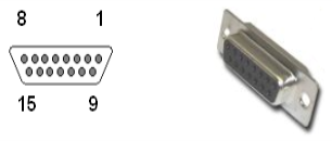
The Facilities Panel includes 8 general purpose optically isolated digital output signals (in addition to those signals that are available at the ZIO Board in the outer link). These lines are accessed in a single DB15 connector.
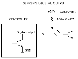
These output signals can be configured as "sinking" or "sourcing." As shipped from the factory, the output signals are configured as "sinking," i.e. the external equipment must provide a 5 VDC to 24 VDC pull-up voltage on an output pin and the controller pulls this pin to ground when the signal is asserted as true. This configuration is compatible with "sourcing" (PNP) devices.
Alternately, the output signals can be configured as "sourcing," i.e. the external equipment must pull-down an output pin to ground and the controller pulls this pin to 24 VDC when the signal is asserted as true. This configuration is compatible with "sinking" (NPN) devices.
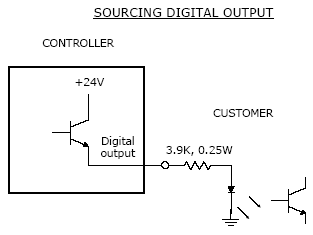
Outputs can be individually configured as sinking or sourcing signals. To configure the output signals, the Controls Bay must be retracted from the J1-axis housing and jumpers on the Guidance Controller must be changed. For more information on configuring the jumpers, please see the Guidance 3000/2000 Controllers, Hardware Introduction and Reference Manual.
|
|
|
|---|---|
| Electrical Shock Hazard | |
|
Contact with electrical power can cause serious personal injury or death. The Guidance 2400, the PrecisePower Intelligent Motor Power Supply, and the 24 VDC power supply are all open frame electrical devices that contain unshielded high voltage pins, components and surfaces. In addition, the motor power supply provides up to 320 VDC volts and takes about two minutes to bleed down after power is disconnected
|

|
The pin out for the Digital Output Connector and the corresponding GPL signal numbers are described in the following table.
| Pin | GPL Signal Number | Description |
|---|---|---|
|
1 |
13 |
Digital Output 1 - When configured as sourcing, this output can drive 500mA, whereas Outputs 2-8 drive 100mA. Starting in 2013, jumpers were added to the controller to permit this signal to drive 500ma or 100ma. By default, this signal is jumpered for 100mA. Prior to 2013, this output always drove 500mA. |
|
2 |
15 |
Digital Output 3 |
|
3 |
|
24 VDC |
|
4 |
17 |
Digital Output 5 |
|
5 |
19 |
Digital Output 7 |
|
6 |
|
Not used |
|
7 |
|
Not used |
|
8 |
|
Not used |
|
9 |
14 |
Digital Output 2 |
|
10 |
16 |
Digital Output 4 |
|
11 |
|
GND |
|
12 |
18 |
Digital Output 6 |
|
13 |
20 |
Digital Output 8 |
|
14 |
|
Not used |
|
15 |
|
Not used |
|
Interface Panel Connector Part No |
|
DB15 Female Connector |
|
User Plug Part No |
|
DB15 Male Plug |