Mount the robot properly and securely before executing this procedure. Additionally, the system must be such that the controller and motor power can be safely enabled.
Cal_PP is a service program that must be run to reset the zero positions of the absolute encoders on each motor. The zero positions must be reestablished if a motor is replaced, if a motor's encoder cable to the controller is disconnected, or if the encoder backup battery located at the controller is replaced.
|
|
|
|---|---|
|
Mount the robot properly and securely before executing this procedure. Additionally, the system must be such that the controller and motor power can be safely enabled. |
|
In order to execute this procedure, the following preconditions must be satisfied:
The following describes the procedure for defining the zero positions of the PreciseFlex robot axes using Cal_PP.
| Step | Action |
|---|---|
|
1. |
Enable power to the robot's controller, and ensure that power to the motors is disabled. |
|
2. |
Load Cal_PP into the controller's memory using either the Guidance Development Environment (GDE) or the web Operator Control Panel. |
|
3. |
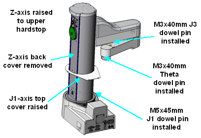
Manually raise the Z-axis so that it is firmly pressed against its upper hard stop limit. |
|
4. |
As shown in the following picture, Rotate the J1-axis so that the inner link is approximately rotated 90 degrees clockwise from the center position as viewed from above.
|
|
5. |
Remove the back cover to the Z-axis to permit the top cover of the J1-axis to be lifted. (Note: This step is not required for newer versions of this robot that have an access hole in the J1-axis top cover that is protected by a "J1 Cal Pin" removable label.) |
|
6. |
Remove the screws to the J1-axis top cover and lift the cover to gain access to the J1 turntable.
NOTE: This step is not required for newer versions of this robot that have an access hole in the J1-axis top cover that is protected by a "J1 Cal Pin" removable label. |
|
7. |
Insert the supplied M5x45 mm dowel pin (through the J1 Cal Pin access hole if present) into the J1-axis turntable and register it with the slot in the base. Rotate the J1-axis clockwise so the pin is pressed against the slot sidewall |
|
8. |
Press one of the supplied M3x40 mm dowel pins into the hole that is in the lower surface of the inner link. Rotate the outer link clockwise so it is pressed against the dowel pin. This should be at 160° on most robots and 90° in a few earlier units. |
|
9. |
If your robot is equipped with a Theta axis, insert one of the supplied M3x40 mm dowel pins into the hole on the Theta flange. Rotate the flange until the pin registers with a slot in the outer link. This should center the flange within its range of travel. |
|
10. |
Execute the Cal_PP program using GDE or the web Operator Control Panel. This program will take just a few minutes to complete. Follow the instructions that are displayed either within GDE or on the Operator Control Panel of the web interface.
|
|
11. |
After Cal_PP has successfully completed, enable motor power (or use the brake release button) and move the Z-axis down from the hard stop. Failing to do this will produce an error as the robot is outside of the soft stop limits. |
|
12. |
Remove the three calibration dowel pins and save them for future use. |
|
13. |
Reattach the J1-axis top cover and the Z-axis back cover or recover the J1 Cal Pin access hole as appropriate. |
The zero position for each of the robot's axes will now be defined and the data required by the homing operation will be stored.