1.
Disconnect the main AC power to the robot.
2.
Detach the robot from its mounting surface. The robot should be gently placed on its side on a protective layer to avoid scratching or damaging the robot's surface.
3.
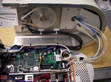
Remove the screws in the Facilities Panel and slide the Controls Bay out of the J1-axis housing. There is no need to disconnect the various cables, just lay the Controls Bay next to the J1 housing as shown below.
4.
|
|
|
|---|---|
| Electrical Shock Hazard | |
|
Contact with electrical power can cause serious personal injury or death. All
of the motors for the PreciseFlex robot are operated
at between 160 VDC and 320 VDC. As such, the motor
wires present a high-risk.
|
|
5.
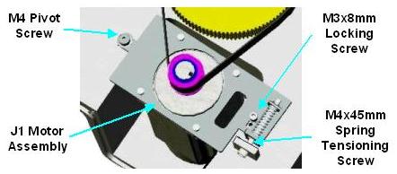
To remove the 1st Stage Belt, remove the M3x8 mm Locking Screw. Then loosen the M4x45 mm Spring Tension Screw to eliminate the tension on the 1st Stage Belt.
6.
Remove the 1st Stage Belt by sliding it off the large pulley and then the J1 Motor flanged pulley.
7.
Detach the J1 Motor Assembly by removing the M4x45 mm Spring Tensioning Screw and the M4 Pivot Screw; and by unplugging the J1 motor and encoder cables at the controller in the Controls Bay.
8.
To install a new J1 Motor Assembly (Precise P/N PF10-MA-00048), the process must be reversed.
9.
First attach the J1 Motor Assembly to the J1 housing at the pivot point (M4 Pivot Screw) using two 5 mm Belleville Washers PP1A-MC-X0025 (MCM 9713K17) seated on a M5 Washer and Fastened with a M4 Shoulder Screw 0000-HC-S0129 (McM 90278A319).
10.
Loosely attach the Tension Screw by inserting a M4x45 mm SHCS though the mounts and a Century BB-90 Spring and retain with a M4 Nut PP1D-MC-X005 (Misumi HNTTBS5-4). Ensure that the Motor Assembly can rotate through it s full range of travel without obstruction.
11.
Slide the 1st Stage Belt over the J1 Motor flanged pulley and the large pulley.
12.
Following the instructions in the next section for setting the 1st Stage Belt tension.
13.
Lock down the rotating Motor Assembly by re-attaching the Locking Screw. This should consist of a M3-8 mm SHCS, M3 washer, and a M3 lock washer.
14.
Re-attach the J1 motor and encoder cables to the controller in the Controls Bay.
15.
Re-install the Controls Bay into the J1 housing and re-mount the robot to the work surface.