All
of the motors for the PreciseFlexTM robot are operated at between
160 VDC and 320 VDC. As such, the motor wires present a high-risk.
- Do not touch unshielded pins and conductors unless the main AC power to the robot is first disconnected.
The 1st Stage Belt for the J3-Axis is located in the Inner Link. To replace or tension this belt, it must be accessed using the same procedures as those described in the section on Replacing the J3-Axis or Theta Motor Assembly. Please review that section prior to performing the following operations.
|
|
|
|---|---|
| Electrical Shock Hazard | |
|
All
of the motors for the PreciseFlexTM robot are operated at between
160 VDC and 320 VDC. As such, the motor wires present a high-risk.
|
|
To replace the belt, you must have available a Gates TruMotion belt (Precise P/N PF10-MC-X0106). Then perform the following operations
| Step | Action |
|---|---|
|
1. |
Follow the instructions in the previous section to remove the Inner Link Cover and the Inner Link Cable Cover. |
|
2. |
Loosen (but do not remove) the J3-Axis Motor Bracket Screws and back off its Jam Nut and Tensioning Bolt. |
|
3. |
Remove the old belt by sliding it over the large pulley and then the motor pulley. |
|
4. |
Install the new belt by placing it around the motor pulley first and then sliding it over the large pulley. |
To properly adjust the tension in the belt, perform the following operations
| Step | Action |
|---|---|
|
1. |
Follow the instructions in the previous section to loosen the J3-Axis Motor Bracket Screws and back off the Jam Nut. |
|
2. |
Measure the belt tension using a Gates Sonic Tension Meter on the more accessible side of the belt. |
|
3. |
Compare the tension to that specified in the Belt Tensioning Table. |
|
4. |
As required, adjust the motor position and belt tension by turning the Tensioning Bolt. |
|
5. |
Tighten the three Motor Bracket Screws and verify that the belt tension is still correct. |
|
6. |
Tighten the Jam Nut to hold the Tensioning Bolt in place. |
|
7. |
Replace the Inner Link Cable Cover and the Inner Link Cover. |
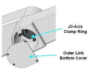
The J3-Axis 2nd Stage Belt is located in the Inner Link. The 2nd Stage Belt drives a large pulley that is affixed to the Outer Link at the robot's elbow and protrudes up through a circular hole in the bottom of the Inner Link. To remove the belt, the Outer Link and large pulley must be dropped relative to the Inner Link. To replace this belt, you must have available a Gates TruMotion Belt (Precise P/N PF10-MC-X0079) and the J3 Removal Tool (Precise P/N PF10-MT-M0001). Then perform the following operations:
| Step | Action |
|---|---|
|
1. |
Remove the J3-Axis 1st Stage Belt by following the instructions in the previous section. |
|
2. |
Remove the J3-Axis 2nd Stage Tension Idler assembly (pictured in Replacing the J3-Axis or Theta Motor Assembly). This can be done by removing the M4 Locking Screw, backing off the Jam Nut and Bolt, and removing the M4 Shoulder screw that retains the pivoting assembly. |
|
3. |
Remove the Outer Link Bottom Cover to gain access to the J3 Clamp Ring. This threaded shaft screws into the Inner Link from below and clamps the J3-Axis output bearings to the Inner and Outer Links at the robot's elbow. |
|
4. |
When the Clamp Ring is installed, Loctite is applied to its threads to lock it to the threads of the Inner Link. To loosen the Clamp ring, use the J3 Removal Tool and a large adjustable wrench to apply enough torque to break the Loctite. |
|
5. |
While supporting the Outer Link, unscrew the Clamp Ring and slide the Clamp Ring down so that it clears the inner races of the J3-Axis output bearings in the elbow. |
|
6. |
Carefully lower the Outer Link so that the large J3-Axis 2nd Stage Belt pulley clears the Inner Link and frees the belt. |
|
7. |
Remove the J3-Axis 2nd Stage Belt by slipping it over 1st Stage pulley. |
|
8. |
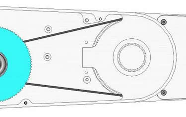
Install the new belt by sliding it over the lower flanged pulley and around the posts as shown below.
|
|
9. |
Carefully slide the Outer Link upwards at an angle so that the large pulley is inserted back into the Inner Link and partially engages the belt. Rotate the Outer Link back and forth until the large pulley fully engages the 2nd Stage Belt. |
|
10. |
Carefully apply a small amount of Loctite 242 to the threads in the Inner Link
NOTE: Make sure that no Loctite contacts the J3-Axis bearings. |
|
11. |
Slide the Clamp Ring and spring through the bearings from below. |
|
12. |
Tighten the Clamp Ring using the J3 Removal Tool. Tighten down until the threads have bottomed out. This ensures the proper preload by the spring into the elbow bearings. |
|
13. |
Verify that the Outer Link rotates smoothly without an excessive amount of friction. |
|
14. |
Re-install the Outer Link Bottom Cover, the J3-Axis 2nd Stage Tension Idler assembly and the J3-Axis 1st Stage Belt. |
|
15. |
Follow the instructions below to properly tension the belt and to reassemble the robot. |
To properly adjust the tension in the belt, perform the following operations:
| Step | Action |
|---|---|
|
1. |
Ensure that Inner Link Cover and the Inner Link Cable Cover are removed, that the J3-Axis 2nd Stage Tension Idler Jam Nut is backed off and that the Idler Locking Screw is removed. |
|
2. |
Measure the belt tension using a Gates Sonic Tension Meter on the side of the belt without the Idler. |
|
3. |
Compare the tension to that specified in the Belt Tensioning Table. |
|
4. |
As required, adjust the belt tension by turning the Jam Bolt to reposition the Idler wheel. |
|
5. |
Tighten the Idler Locking Screw and verify that the belt tension is still correct. |
|
6. |
Tighten the Jam Nut to hold the Jam Bolt in place. |
|
7. |
Re-attach the Inner Link Cable Cover and the Inner Link Cover. |