
PreciseFlex robots are equipped with communication interface boards (MCIMs) that include an Ethernet switch that implements two 10/100 Mbit Ethernet ports. This capability was designed to permit the controller to be interfaced to multiple Ethernet devices such as other PreciseFlex controllers or robots, remote I/O units and Ethernet cameras. The Ethernet switch automatically detects the sense of each connection, so either straight-thru or cross-over cables can be used to connect the controller to any other Ethernet device.
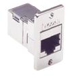
Due to limited space on the X-Axis Facilities Panel, only one of the two Ethernet ports (Figure 38-164) is available via an external RJ45 connector (Figure 38-165). This external Ethernet port is typically used to interface the robot to a PC
|
|
|
As a convenience for Ethernet devices that are mounted on the Z-axis of the robot, the second Ethernet port is connected to an optional Ethernet cable that is routed through the interior of the robot. One end of this cable is plugged into the robot controller's Ethernet switch and the other end is under the cover for the Z-axis motor. Any device that is plugged into this cable, such as an Ethernet camera mounted on the Z-axis, can also communicated with units that are plugged into the RJ45 on the Facilities Panel. So, a PC that is connected to the Ethernet plug on the Facilities Panel can communicate with the robot’s controller as well as receive images from an arm-mounted camera.
If an Ethernet camera is mounted in the workcell, an external Ethernet switch must be added to connect these cameras and the robot to a PC.
See the Guidance Controller Quick Start Guide User Manual for instructions on setting the IP address for the controller.