Open topic with navigation
Z-Axis and Z-Axis IO PCB
The Z-axis is composed of a motor carriage,
an extrusion, end caps, a sliding cover, a status light, and an IO Printed Circuit Board
(Rev 2 version of the ZIO, “ZIO2”). The Z motion
drive consists of a timing belt reduction and main drive belt attached to
the Z stage. The Z motor includes a fail-safe brake that can be manually
released by pressing a button on the side of the ZIO2 Board.
The ZIO2 PCB serves as a connector board for
motor and encoder signals and provides 8 isolated user digital input and
8 isolated user digital output signals. It also supports a robot
status light, and an optional power supply and connectors for the arm mounted
Ethernet camera and ring light option. For I/O control, this board is connected
to the robot’s controller by an RS485
serial line that allows the I/O to be scanned with a nominal period of 4
milliseconds.
Figure 62-127 illustrates the position of each of the key connectors
on the board.
|
Contact with electrical power can cause serious personal injury or death. A
motor connector that provides a bus voltage of 320 VDC is
positioned near the ZIO2. As such, accessing this board represents
a high-risk
- Disconnect the main AC power to the robot before accessing this board.
|

|
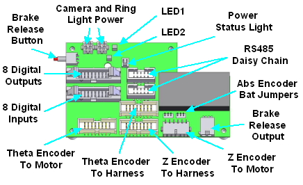
Figure 62-127: Position of Key Connectors on Board
In Table 62-90, each of the connectors is
briefly described. For application interfaces, such as the
digital output signals,
pin assignments are described in detail in subsequent tables.
Table 62-90: Connectors
| Connector
|
Description
|
|
Abs Encoder Bat Jumpers
|
On newer boards, these jumpers are present and are factory set depending
upon whether the Z-axis has hall effect
sensors or an absolute encoder that requires battery power.
|
|
Brake Release Button / Output
|
The Brake Release Output is wired to the fail-safe brake on the Z-axis
motor. This brake prevents the axis from falling when power
is off. Normally,
this brake is automatically controlled by the system software. If
the Brake Release Button is pressed, the brake can be manually released
so long as power is provided to the robot's controller.
|
|
Camera Power / Light Power
|
If the optional Arm Mounted Camera Kit is purchased, these connectors
provide power to the camera and the camera's ring light. The
camera power is always available whenever the robot's controller is
powered on. The ring light power can be turned on and off via
software control. Two identical connectors are provided to simplify
wiring.
|
|
Digital Inputs / Digital Outputs
|
These provide 8 optically isolated user input and 8 optically isolated
user output signals. These signals are available to interface
to tooling and sensors mounted on the end of the robot. These
signals are described in detail below.
|
|
LED1 (Activity / Error)
|
Green - Blinks fast (about 10 Hz) when the ZIO2 is not communicating
with the robot's controller. Blinks slowly (about 1 Hz) during
normal communication.
Red - Off at initial power-up and during normal communications. On if communications
is lost after being established.
|
|
LED2 (Camera light)
|
Green - Tracks the state of the camera ring light power.
Red - No currently used.
|
|
Power Status Light
|
This connects to an LED mounted in the top of the Z-axis cover. (See below for more information.)
|
|
RS485 Daisy Chain
|
The RS485 interface is a multi-drop high speed serial interface that
permits the robot controller to operate the digital input and output
signals on the ZIO2 board. Two identical connectors are provided
to permit the RS485 signals to be daisy-chained to other RS485 devices
mounted on the end of the robot.
|
|
Theta Encoder To Harness/Motor
|
These are two pass through connectors that interface the Theta (4th)
axis encoder to the appropriate signals in the robot harness. The Theta
encoder internal harness connector should be plugged into the "To Harness"
board connector. If a Theta axis is present, its encoder should
be plugged into the "To Motor" connector.
|
|
Z Encoder To Harness/Motor
|
These are two pass through connectors that interface the Z (3rd)
axis encoder to the appropriate signals in the robot harness. The Z-axis
encoder internal harness connector should be plugged into the "To
Harness" board connector. The Z-axis encoder should
be plugged into the "To Motor" connector.
|
The 8 isolated digital input and 8 isolated digital
output signals provided on the ZIO2 are intended for interfacing to tooling
and sensors mounted on the end of the robot or for other general application
needs. These
DIO signals are in addition to those available on the X-axis Facilities Panel
of the robot. These signals are provided in two 16-pin connectors (Figure 62-128).
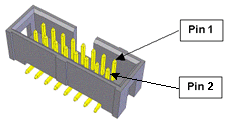
Figure 62-128: Sixteen-Pin Connector
The 8 digital input signals are configured
as "sinking" (Figure 62-129), that is, the external equipment must supply a 5 VDC to 24 VDC voltage to
indicate a logical high value or must allow it to float to no voltage for
a logical low. For convenience, 24 VDC is supplied on the digital input
signal connector. These inputs are compatible
with "sourcing" (PNP) sensors.
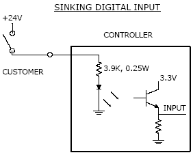
Figure 62-129: Sinking Input
The 8 digital output signals are configured
as "sourcing" (Figure 62-130), that is, the external equipment must pull-down
an output pin to ground and the ZIO2 pulls this pin to 24 VDC when
the signal is asserted as true. Each output signal can supply a maximum
of 100mA. For convenience, ground pins are supplied on the digital output
signal connector. These outputs are
compatible with "sinking" (NPN) devices.
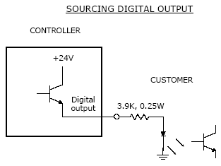
Figure 62-130: Sourcing Output
The pin assignments for these two connectors
are defined in Table 62-91 and Table 62-92 along with the signal numbers used to
reference these signals from GPL and the part number for the required hardware
plugs
As
of November 2008, the ZIO board's Digital Input 8
failed the CE 10 volts per meter Radiated RF Immunity test. Therefore,
until this has been corrected, for CE applications, only
ZIO inputs bits 1-7 may be used
Table 62-91: Pin Assignments with Digital Input
|
Pin |
GPL Signal Number
|
Description
|
|
1
|
10033
|
Digital Input 1
|
|
2
|
10037
|
Digital Input 5
|
|
3
|
10034
|
Digital Input 2
|
|
4
|
10038
|
Digital Input 6
|
|
5
|
10035
|
Digital Input 3
|
|
6
|
10039
|
Digital Input 7
|
|
7
|
10036
|
Digital Input 4
|
|
8
|
10040
|
Digital Input 8
|
|
9 to 16
|
|
24 VDC
|
|
User Plug Part No
|
|
Amp 746285-3 or Molex 22-55-2161 or Molex 90142-0016. For the Molex plugs, use Molex pins 16-02-0103 and Molex crimp tool 63811-1000.
|
|
High Flex Cable
|
|
A high flex cable should be used to ensure long life. We recommend
3M Round Conductor High Flex Life Flat Cable, 28 AWG stranded, PVC,
3319/16 or Amphenol Spectra-Flex high flex life flat cable 843-191-2811-016.
|
Table 62-92: Pin Assignments with Digital Ouput
|
Pin
|
GPL Signal Number
|
Description
|
|
1
|
33
|
Digital Output 1
|
|
2
|
37
|
Digital Output 5
|
|
3
|
34
|
Digital Output 2
|
|
4
|
38
|
Digital Output 6
|
|
5
|
35
|
Digital Output 3
|
|
6
|
39
|
Digital Output 7
|
|
7
|
36
|
Digital Output 4
|
|
8
|
40
|
Digital Output 8
|
|
9
to 16
|
|
Ground
|
|
User Plug Part No
|
|
Amp 746285-3 or Molex 22-55-2161 or Molex 90142-0016. For the Molex plugs, use Molex pins 16-02-0103 and Molex crimp tool 63811-1000.
|
|
High Flex Cable
|
|
A high flex cable should be used to ensure long life. We recommend
3M Round Conductor High Flex Life Flat Cable, 28 AWG stranded, PVC,
3319/16 or Amphenol Spectra-Flex high flex life flat cable 843-191-2811-016.
|
There are two four-pin connectors (Figure 62-131) that provide power
for an Ethernet camera and camera ring light if the Arm Mounted Camera Kit is installed.
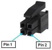
Figure 62-131: Four-Pin Connector
The pin assignments for these connectors
are defined inTable 62-93 along with the part number for the required
plug type. Two connectors provide identical signals as a wiring convenience.
Table 62-93: Pin Assignments
|
Pin |
GPL Signal Number |
Description
|
|
1
|
|
12 VDC for powering camera, 1.25 A total current is shared between
two connectors.
|
|
2
|
|
Ground
|
|
3
|
8039
|
9 VDC for powering ring light. Enabled and disabled
via a dedicated system IO signal or via the robot ZIO control panel in
the Web Operator Interface. 1 A
total current is shared between two connectors.
|
|
4
|
|
Ground
|
|
User Plug Part No
|
|
AMP 794617-4. Use
an AMP 91501-1 hand crimp tool and AMP 1-794610-2 sockets for wiring
to the plug.
|
If the yellow Outer Link status LED is configured as normally shipped from the factory, Table 62-94 describes how to interpret each light pattern.
Table 62-94: Light Pattern
| Status LED |
Description
|
|
Continuously Off
|
AC power off or processor crashed. Either the AC power is off or the processor has crashed due to a system hardware or software error. If the processor has crashed, it may be executing the firmware debugger, dBug.
|
|
Continuously On
|
Booting sequence. AC power is on and the firmware and software are being loaded. The LED begins blinking when the system is up and running.
Process crashed. If the LED turns on continuously after it has been blinking, the processor has crashed due to a system hardware or software error. The processor may be executing the firmware debugger, dBug.
|
|
Blinks 1 times per second
|
Normal operation, motor power off.
|
|
Blinks 4 times per second
|
Normal operation, motor power on.
|
|
Blinks 8 times per second
|
Processor overheating, motor power off. There are five minutes to save any programs or data. After five minutes, the processor will shut down and it will need to be rebooted.
|