Many Guidance Controllers can be optionally supplied with either four or six instrument-grade Digital to Analog Converter (DAC) output channels. These DACs are primarily intended to interface the controller to 3rd party, external motor amplifiers (although they can be utilized as general analog output signals). These external amplifiers can be used in place of or in combination with the controller's integrated motor drives. The signals for the first four DAC channels are provided on a single connector (see Figure 7-46). If supplied, the signals for the next two DAC channels are provided on the Auto/Man Daisy Chain connector.
Each of the DACs has an output range of +/- 10VDC. The DAC values have a resolution of 16 bits and are monotonic to 16 bits as well. They have a settling time of approximately 10 usec. Associated with each DAC channel is an "AMP ENABLE" digital output signal and an "AMP FAULT" digital input signal. The amp enable allows the controller to individually turn on the power to motors. The amp fault signals aid in isolating hardware problems. For the amp enable and amp fault signals, high values are at 24VDC. Figure 7-47 and Figure 7-48 illustrate how to wire the AMP ENABLE digital output signals for the first channel in both sinking and sourcing configurations. The AMP ENABLE signals for channels 2 to 6 can be wired in an analogous manner.
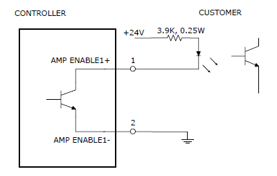
Figure 7-47: Amplifier Enable Output Wired as Sinking Output
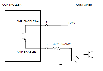
Figure 7-48: Amplifier Enable Output Wired as Sourcing Output
Figure 7-49 and Figure 7-50 illustrate how to wire the AMP FAULT input signals for the first channel in both sinking and sourcing configurations. The AMP FAULT signals for channels 2 to 6 can be wired in an analogous manner.
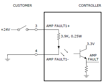
Figure 7-49: Amplifier Fault Input Wired as Sinking Input
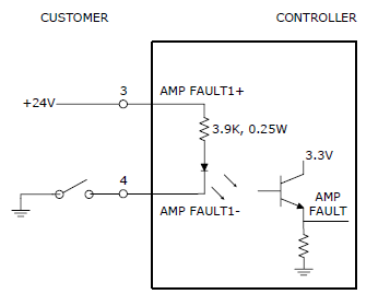
Figure 7-50: Amplifier Fault Input Wired as Sourcing Input
Table 7-38 details the pinout for the primary analog output connector.
| Pin | Description |
|---|---|
|
1 |
24VDC AMP ENABLE1 + |
|
2 |
24VDC AMP ENABLE1 - |
|
3 |
24VDC AMP FAULT1 + |
|
4 |
24VDC AMP FAULT1 - |
|
5 |
+/- 10VDC DAC1+ |
|
6 |
+/- 10VDC DAC1- |
|
7 |
24VDC AMP ENABLE2 + |
|
8 |
24VDC AMP ENABLE2 - |
|
9 |
24VDC AMP FAULT2 + |
|
10 |
24VDC AMP FAULT2 - |
|
11 |
+/- 10VDC DAC2+ |
|
12 |
+/- 10VDC DAC2- |
|
13 |
24VDC AMP ENABLE3 + |
|
14 |
24VDC AMP ENABLE3 - |
|
15 |
24VDC AMP FAULT3 + |
|
16 |
24VDC AMP FAULT3 - |
|
17 |
+/- 10VDC DAC3+ |
|
18 |
+/- 10VDC DAC3- |
|
19 |
24VDC AMP ENABLE4 + |
|
20 |
24VDC AMP ENABLE4 - |
|
21 |
24VDC AMP FAULT4 + |
|
22 |
24VDC AMP FAULT4 - |
|
23 |
+/- 10VDC DAC4+ |
|
24 |
+/- 10VDC DAC4- |
|
User Plug Part No |
Amp 746285-5 or Molex 22-55-2241 or Molex 90142-0024. For the Molex plugs, use Molex pins 16-02-0103 and Molex crimp tool 63811-1000. |