
All communication interface boards provide twelve general purpose optically isolated digital input signals that are accessed in a single IDC connector. This type of connector permits these signals to be easily interfaced to other devices. See Figure 7-51.
By setting three sets of Sinking Versus Sourcing Jumpers, these inputs can be configured as either "sinking" or "sourcing" in groups of four signals.
If an input signal is configured as "sinking" (Figure 7-52), the external equipment must provide a 5VDC to 24VDC voltage to indicate a logical high value or no voltage for a logical low. This configuration is compatible with "sourcing" (PNP) sensors.
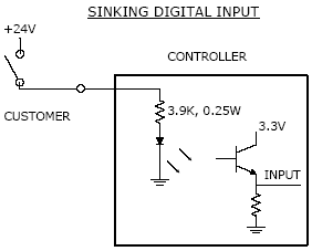
Figure 7-52: Sinking Input Signal
If an input signal is configured as "sourcing" (Figure 7-53), the external equipment must pull the signal input pin to ground to indicate a logical high and must let the line float high to 24VDC to signal a logical low value. This configuration is compatible with "sinking" (NPN) sensors.
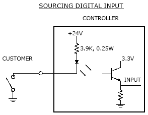
Figure 7-53: Sourcing Input Signal
NOTE: As shipped from the factory, all digital inputs are normally configured as "sourcing."
The pinout for the Digital Input Connector and the corresponding GPL signal numbers are described in Table 7-39.
| Pin | GPL Signal Number | Description |
|---|---|---|
|
1 |
|
24VDC |
|
2 |
|
GND |
|
3 |
10001 |
Digital Input 1 |
|
4 |
10002 |
Digital Input 2 |
|
5 |
10003 |
Digital Input 3 |
|
6 |
10004 |
Digital Input 4 |
|
7 |
10005 |
Digital Input 5 |
|
8 |
10006 |
Digital Input 6 |
|
9 |
10007 |
Digital Input 7 |
|
10 |
10008 |
Digital Input 8 |
|
11 |
10009 |
Digital Input 9 |
|
12 |
10010 |
Digital Input 10 |
|
13 |
10011 |
Digital Input 11 |
|
14 |
10012 |
Digital Input 12 |
|
15 |
|
24VDC |
|
16 |
|
GND |
|
User Plug Part No |
|
Amp 746285-3 or Molex 22-55-2161 or Molex 90142-0016. For the Molex plugs, use Molex pins 16-02-0103 and Molex crimp tool 63811-1000. |