All communication interface boards provide eight general- purpose optically isolated digital output signals that are accessed in a single IDC connector (Figure 7-54). This type of connector permits these signals to be easily interfaced to other devices.
By setting eight sets of Sinking Versus Sourcing Jumpers, each output can be individually configured as either "sinking" or "sourcing." If an output signal is "sinking" (Figure 7-55), the external equipment must provide a 5VDC to 24VDC pull-up voltage on the output pin and the controller pulls this pin to ground when the signal is asserted as true. This configuration is compatible with "sourcing" (PNP) devices.
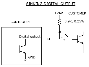
Figure 7-55: Sinking Output Signal
If an output signal is "sourcing" (Figure 7-56), the external equipment must pull-down the output pin to ground and the controller pulls this pin to 24VDC when the signal is asserted as true. This configuration is compatible with "sinking" (NPN) devices.
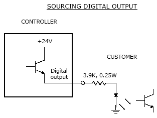
Figure 7-56: Sourcing Output Signal
NOTE: As shipped from the factory, all digital outputs are normally configured as "sinking."
Table 7-40 decribes the pinout for the Digital Output Connector and the corresponding GPL signal numbers.
| Pin | GPL Signal Number | Description |
|---|---|---|
|
1 |
13 |
Digital Output 1 - For most controllers, when configured as sourcing, this output drives 500mA, whereas Outputs 2-8 drive 100mA. Starting in 2013, for the G2xxxC controllers only, jumpers were added to permit this signal to drive 500ma or 100ma. For this controller, by default, this signal is jumpered for 100mA. |
|
2 |
14 |
Digital Output 2 |
|
3 |
15 |
Digital Output 3 |
|
4 |
16 |
Digital Output 4 |
|
5 |
|
24VDC |
|
6 |
|
GND |
|
7 |
17 |
Digital Output 5 |
|
8 |
18 |
Digital Output 6 |
|
9 |
19 |
Digital Output 7 |
|
10 |
20 |
Digital Output 8 |
|
User Plug Part No |
|
AMP 746285-1 or Molex 22-55-2101 or 90142-0010. For the Molex plug, use Molex pins 16-02-0103 and Molex crimp tool 63811-1000. |