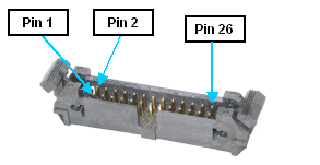
The GIO board provides twelve (12) general purpose optically-isolated digital input signals and eight (8) general purpose optically isolated digital output signals. These signals are presented in a single 26-pin IDC compatible connector with retaining latches. This type of connector permits these signals to be easily interfaced to other devices.
Figure 57-2: 26-pin IDC Compatible Connector with Retaining Latches
Depending upon the setting of the Sinking Versus Sourcing Inputs Jumpers (J3, J4, J5), the inputs are configured as "sinking" or "sourcing" in groups of 4 signals. J3 configures inputs 1-4, J4 configures inputs 5-8, and J5 configures inputs 9-12.
If an input signal is configured as "sinking," the external equipment must provide a 5VDC to 24VDC voltage to indicate a logical high value or no voltage for a logical low. This configuration is compatible with "sourcing" (PNP) sensors.

Figure 57-3: Sinking Digital Input
If an input signal is configured as "sourcing," the external equipment must pull the signal input pin to ground to indicate a logical high and must let the line float high to 24VDC to signal a logical low value. This configuration is compatible with "sinking" (NPN) sensors.
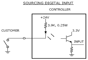
Figure 57-4: Sourcing Digital Input
As shipped from the factory, all digital inputs are normally configured as "sourcing."
By setting eight (8) sets of Sinking Versus Sourcing Output Jumpers (J11), each output can be individually configured as either "sinking" or "sourcing."
If an output signal is "sinking," the external equipment must provide a 5VDC to 24VDC pull-up voltage on the output pin and the GIO pulls this pin to ground when the signal is asserted as true. This configuration is compatible with "sourcing" (PNP) devices.
![]()
Figure 57-5: Sinking Digital Output
If an output signal is "sourcing," the external equipment must pull-down the output pin to ground and the GIO pulls this pin to 24VDC when the signal is asserted as true. This configuration is compatible with "sinking" (NPN) devices.
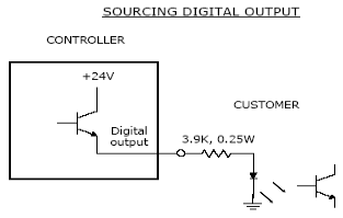
Figure 57-6: Sourcing Digital Output
As shipped from the factory, all digital outputs are normally configured as "sinking."
The pin out for the Digital Input and Output Connector and the corresponding GPL signal numbers are described in the following table. For the GPL signal numbers "n" is the GIO's Network Node number that is defined when configuring the controller, not the GIO's unit number.
If the GIO board is installed within an enclosure, it is often convenient to use a ribbon cable whose ends are terminated with an IDC plug and a female DB25 connector to present the digital input and output signals on the enclosure's facilities panel. For example, if a GIO is installed inside a PreciseFlex™ 400 Sample Handler, this type of cable is used to connect the GIO to a DB25 plug that can be accessed from the outside at the base of the robot.
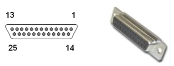
In this case, the 26th pin of the GIO's Digital Input and Output Signals Connector is not utilized. The pin numbers for the signals are changed due to the DB25 pin numbering scheme. The revised pin numbers and the corresponding GPL signal numbers are described in Table 57-2. For the GPL signal numbers "n" is the GIO's Network Node number that is defined when configuring the controller, not the GIO's unit number.