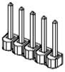
The GIO board has a number of hardware jumpers that determine the configuration of various hardware functions. Depending upon the type of jumper, there may be two, three or five jumper posts. Posts are tied (shorted) together using black jumper plugs. The five (5) wide jumper posts for configuring the digital output signals are shown in Figure 57-12.
Figure 57-12: GIO Board Jumpers
The locations of each of the key sets of jumpers are illustrated in Figure 57-13 and are identified by stenciled labels on the surface of the GIO board.
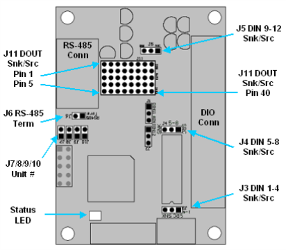
Figure 57-13: Locations of Key Sets of Jumpers
Table 57-6 describes each of the sets of jumpers and how the pins must be shorted ("jumpered") in order to set a specific configuration. When a direction (e.g. left verses right) is described, it is with respect to the GIO board oriented as shown in Figure 57-13.
|
Jumpers |
Description |
Setting |
|---|---|---|
|
J11 Digital Outputs Sink/Source |
These jumpers determine if each of the Digital Output Signals is "sinking" or "sourcing." This array of jumpers consists of eight (8) columns of five (5) posts. Each column determines the setting for a single digital output. The left column (pins 1-5) control to the first digital output signal. To set an output to sourcing, two(2) jumpers must be installed on the top four (4) posts. To set an output to sinking, two (2) jumpers must be installed on the bottom four (4) posts. For example, to set the first output to sinking, a jumper should short pins 2 and 3 and a second jumper should short pins 4 and 5. NOTE: As shipped from the factory, all outputs are set to sinking. |
For sinking, short bottom four posts using two jumpers |
|
J10 Spare Jumper |
This is the right most jumper in the J7/J8/J9/J10 group and is currently unused. NOTE: As shipped from the factory, this jumper always is installed. |
Always installed |
|
J7/J8/J9 Unit Number |
In the low-level RS-485 communication protocol, the Unit Number determines which GIO is the originator or recipient of each message, not the position of the GIO board in the RS-485 daisy chain. See the Unit Number Jumper section for a description of these jumpers. The left most jumper is J7. NOTE: As shipped from the factory, all three (3) of these jumpers are installed and the board is set to unit #1. |
Install or remove to define GIO Unit Number. |
|
J6 RS-485 Bus Termination |
This jumper controls if RS-485 Bus Termination is enabled on this board. For reliable communications, if a GIO is at the end of a RS-485 daisy chain, this jumper must be installed to terminate the communication line. If a GIO is in the middle of a RS-485 daisy chain, this jumper must be uninstalled to disable the termination. NOTE: As shipped from the factory, this jumper is installed and the GIO should be installed at the end of the RS-485 daisy chain. |
Install jumper J6 to terminate the RS-485 communication lines. |
|
J3/J4/J5 Digital Inputs Sink/Source |
These jumpers configure the "sinking" or "sourcing" mode of operation for the Digital Input Signals in groups of four (4). J3 configures inputs 1-4, J4 configures inputs 5-8, and J5 configures inputs 9-12. Each jumper consists of three (3) posts. If the left posts are jumpered, the group of input signals is configured as sinking. If the right posts are jumpered, the group of inputs is configured as sourcing. NOTE: As shipped from the factory, all inputs are set to sourcing. |
For Sinking, |
|
This is a green and red LED that blinks to indicate the operational status of the controller. |
|