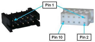
As a standard feature, the Guidance 1000 provides four general-purpose, optically isolated digital input signals and four-general purpose, optically isolated digital output signals. These signals are presented in a single 10-pin JST S10B-PHDSS(LF)(SN) connector that mates with a JST PHDR-10VS plug.
Figure 62-63: JST S10B-PHDSS(LF)(SN) Connector and JST PHDR-10VS Plug
By setting Jumpers on the CPU (MIDS2) board, the four (4) output signals can be individually configured as "sinking" or "sourcing" and the four digital inputs can be configured as a group to all operate as either sinking or sourcing.
If an input signal is configured as "sinking," the external equipment must provide a 5VDC to 24VDC voltage to indicate a logical high value or no voltage for a logical low. This configuration is compatible with "sourcing" (PNP) sensors.
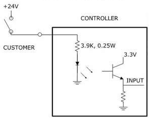
Figure 62-64: Sinking Digital Input
If an input signal is configured as "sourcing," the external equipment must pull the signal input pin to ground to indicate a logical high and must let the line float high to 24VDC to signal a logical low value. This configuration is compatible with "sinking" (NPN) sensors.
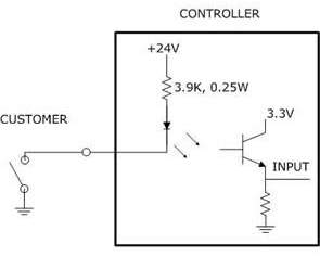
Figure 62-65: Sourcing Digital Input
If an output signal is "sinking," the external equipment must provide a 5VDC to 24VDC pull-up voltage on the output pin and the controller pulls this pin to ground when the signal is asserted as true. This configuration is compatible with "sourcing" (PNP) devices.
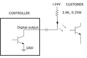
Figure 62-66: Sinking Digital Output
If an output signal is "sourcing," the external equipment must pull-down the output pin to ground and the controller pulls this pin to 24VDC when the signal is asserted as true. This configuration is compatible with "sinking" (NPN) devices.
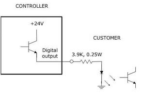
Figure 62-67: Sourcing Digital Output
NOTE: As shipped from the factory, all digital inputs are normally configured as "sourcing" and all outputs are configured as "sinking."
The pin out for the Digital Input and Output Connector and the corresponding GPL signal numbers are described in Table 62-55.
| Pin | GPL Signal Number | Description |
|---|---|---|
|
1 |
13 |
Digital Output 1 |
|
2 |
14 |
Digital Output 2 |
|
3 |
15 |
Digital Output 3 |
|
4 |
16 |
Digital Output 4 |
|
5 |
|
GND |
|
6 |
|
24VDC output |
|
7 |
10001 |
Digital Input 1 |
|
8 |
10002 |
Digital Input 2 |
|
9 |
10003 |
Digital Input 3 |
|
10 |
10004 |
Digital Input 4 |
|
User Plug Part No |
|
JST PHDR-10VS. For this plug, use JST SPHD-002T-P0.5 pins. |