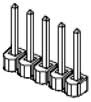
The high performance processor board (MIDS2) has a number of hardware jumpers that determine the configuration of some basic system hardware and software functions. Depending upon the jumper type, there may be two, three, or five posts. Posts are tied (shorted) together using black jumper plugs. The five wide jumper posts for configuring the digital output signals are shown in Figure 62-78.
The locations of each of the sets of jumpers of interest are illustrated in Figure 62-79 and are identified by stenciled labels on the surface of the MIDS2 board.
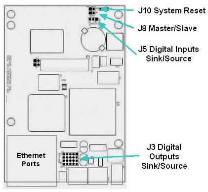
Figure 62-79: Jumper Locations
Table 62-66 describes each of the sets of jumpers and how the pins must be shorted ("jumpered") in order to set a specific configuration. When a direction (e.g. left verses right) is described, it is with respect to the MIDS2 board oriented as shown in Figure 62-79.
| Jumpers | Description | Setting |
|---|---|---|
|
J10 System Reset |
If a jumper is installed on these two posts, when the system is restarted, the default configuration files (*.PAC) are applied instead of the standard files. This setting is utilized if a configuration file becomes corrupted or a setting inadvertently makes the system unusable. As shipped from the factory, this jumper is not installed. |
Install jumper J10 to reset the system. |
|
J8 Master / Slave |
This jumper determines if the controller operates in Master or Slave node in a multiple controller servo network. If the controller operates by itself, it should be set in Master mode. As shipped from the factory, this jumper is not installed and indicates Master mode. |
Install jumper J8 to select Slave mode |
|
J5 Digital Inputs Sink/Source |
These jumpers determine if all four of the Standard General Purpose Digital Input Signals are "sinking" or "sourcing." There is just one set of three posts and their setting dictates the behavior of all four inputs. Pin 1 is to the right-most post and pin 3 is to the left-most. As shipped from the factory, the inputs are set to sourcing. |
For Sinking, |
|
J3 Digital Outputs Sink/Source |
These jumpers determine if each of the Standard General Purpose Digital Output Signals is "sinking" or "sourcing." These jumpers consist of four rows of five posts. Each row determines the setting for a single digital output. The top row corresponds to the first digital output signal. Two jumpers must be set in each row. Within each row, pin 1 is the right-most post and pin 5 is the left-most. As shipped from the factory, the outputs are set to sinking. |
For Sinking, |