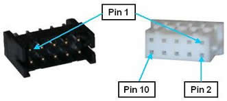
Guidance 1000 controllers are equipped with 2, 3, or 4 encoder interfaces to match the number of motor drives included. Each interface is provided in a single 10-pin JST S10B-PHDSS(LF)(SN) connector that mates with a JST PHDR-10VS plug.
Figure 62-70: Ten-pin JST S10B-PHDSS(LF)(SN) Connector and JST PHDR-10VS Plug
Each interface can be configured for a differential or single-ended incremental encoder or a variety of absolute encoders. Since many absolute encoders require external battery backup power to retain the memory of their revolutions counters, each encoder interface includes a battery power line that is directly connected to the Motor Power In Connector. See the "Third Party Equipment" section of this manual for more information on configuring and wiring absolute encoders. Also, note that certain absolute encoders require the "Enhanced" version of the Guidance Controller due to special hardware requirements.
NOTE: Review the Installation section of this manual for recommendations on best practices for wiring encoders.
Following the provided instructions will significantly reduce the likelihood of any problems due to noise in the encoder signals.
The pin out for the Encoder Connector is described in Table 62-58.
| Pin | Description |
|---|---|
|
1 |
5VDC output provided to power encoders. The sum of the current drawn from all four encoder connectors is limited to 360 mA. |
|
2 |
Encoder A+ |
|
3 |
Encoder A- |
|
4 |
Absolute encoder battery+ output |
|
5 |
Encoder B+ |
|
6 |
Encoder B- |
|
7 |
GND |
|
8 |
Encoder Z+ |
|
9 |
Encoder Z- |
|
10 |
GND |
|
User Plug Part No |
JST PHDR-10VS. For this plug, use JST SPHD-002T-P0.5 pins. |