The power to drive the motors must be supplied separately from the logic power. The logic power must be 24VDC and must be continuously on while the controller is operational. The motor power can range from 12VDC to 42VDC and is turned on and off whenever the robot is enabled or disabled.
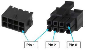
The power to drive the motors and any required battery backup power needed for absolute encoders is supplied via the Motor Power Input Connector. This connector is an 8-pin AMP 3-794618-8 that mates with a AMP 794617-8 plug.
Figure 62-73: Eight-pin AMP 3-794618-8 Connector and AMP 794617-8 Plug
As a convenience, this connector includes "Enable amplifier +/-" signals that permit the motor power supply to be left on continuously. These signals can disable the power amplifiers and internally cut off power to the motors. This is convenient to power both the logic and the motors from the same 24VDC power supply and the supply is able to absorb the energy pump up when the robot is decelerating.
To enable the motor amplifiers, the following signals pins must be connected:
2-3, 6-7
See the Connecting Power and Enabling Motor Power section of this manual for general information concerning enabling motor power.
Since many absolute encoders require external battery backup power to retain the memory of their revolutions counters, this connector provides a means for connecting a battery to the system. Any battery power provided on these pins is directly routed to each Encoder Interface Connector. See the "Third Party Equipment" section of this manual for more information on configuring and wiring absolute encoders. Note that certain absolute encoders require the "Enhanced" version of the Guidance Controller due to special hardware requirements.
The pin out for the Motor Power Input Connector is described in Table 62-60.
| Pin | Description |
|---|---|
|
1 |
Motor power input, 12VDC to 42VDC nominal. |
|
2 |
24VDC output. |
|
3 |
Motor amplifier enable+. Connected to pin 2 to enable the amplifiers. |
|
4 |
Absolute encoder battery+ input |
|
5 |
GND |
|
6 |
GND. |
|
7 |
Motor amplifier enable- Connected to pin 6 to enable the amplifiers. |
|
8 |
Absolute encoder battery- input |
|
User Plug Part No |
AMP 794617-8. Use an AMP 91501-1 hand tool and AMP 1-794610-2 sockets for wiring to the plug. |