The communication boards include a LED that indicates the status of the controller by blinking. The execution conditions that are indicated by the LED are described in the Status LED and Status Output Signal section of this manual.
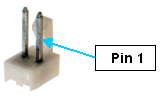
If the controller is embedded, an external LED can be connected to a General Digital Output Signal and the blinking function can be mapped to the signal. As a convenience, the 8th General Digital Output Signal is duplicated in a two-pin header (Figure 7-70). This permits an LED to be easily wired to the controller without having to breakout this one signal from the General Digital Outputs Connector.
To configure the 8th Digital Output Signal to blink in synchronization with to the controller status, the "Power State DOUT" (DataID 235) value in the controller's Parameter Database should be set to "20." In addition, as shipped from the factory, the 8th Digital Output Signal is configured as "sinking." In order to drive an LED, this signal must be configured as "sourcing." See the section on Sinking Versus Sourcing Jumpers for information on reconfiguring this signal. Also see Table 7-51.
| Pin | GPL Signal Number | Description |
|---|---|---|
|
1 |
20 |
Digital Output 8 |
|
2 |
|
GND |
|
User Plug Part No |
|
Molex 22-01-2021 mates to Molex 22-23-2021 Header |