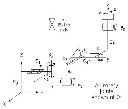
This module controls a 4-axis robot with all rotary actuators or a 5-axis robot that includes a first linear drive that moves the robot along the World Y-axis. The 4-axis configuration is a simplified version of what is commonly referred to as an "Articulated" robot. The first axis rotates the robot about the World Z-axis. The next two axes rotate the inner and outer links about horizontal axes. The combination of the first three axes position the wrist at a desired X, Y, Z location. The last rotary wrist axes controls the pitch of the tool flange relative to the orientation defined by the first three axes. If the optional linear drive is included, both the yaw and the pitch orientation of the wrist can be controlled.
NOTE: The 5-axis version of this kinematic module has been completed, but the 4-axis version has not yet been developed.
This module can be optionally configured to control an "Extra" independent axis. This axis does not factor into the computation of the Cartesian (XYZ) position of the robot, but its motion can be synchronized with the motion of the primary axes. In addition, the 3rd, 4th, and 6th axes can be configured to operate in Split-axis control mode whereby two motors run in unison to drive the selected axis.
The 4-axis geometry is most useful in applications where operations are primary in the vertical direction and limited orientation capability is required. The 5-axis geometry is an unusual configuration that is appropriate for some specialized inspection applications.
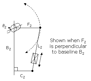
As an option, the first rotary axis (q2) can be configured to be driven by a linear actuator. This type of drive has a limited range of travel and lower speeds but can produce very high torques with modestly sized motors. At the GPL application level, this rotary axis is still controlled in units of degrees. At the motor/encoder level, the control is in units of encoder counts for the linear actuator. The following drawing illustrates the additional dimensional parameters that are necessary to specify the conversion between angles and motor encoder counts.
Kinematics Module Number and Required Software License
Module number to be entered into the "Robot type" (DataID 116): 17
Required software kinematic license (entered using the web interface panel Utilities > Controller Options if not already installed): Complex Kinematics.
Kinematic Model
Axis Optional Max Range Description 1: S1
Yes
Unlimited
Optional linear axis that moves the robot in the direction of the World Y-axis. A positive change in this axis position results in a movement in the direction of the positive World Y-axis.
2: q2
No
+/- 359.9°
(unless rotary / linear drive)Rotary axis that rotates the robot about the direction of the World Z-axis. A positive change in the axis angle results in a positive rotation about the direction of the World Z-axis. If this rotary axis is actuated by a linear drive, the full range of travel must be less than 180 degrees. The center of this axis' travel can be arbitrarily set, although it is typically centered about 0, 180 or -180 degrees.
3: q3
No
+/- 359.9°
Rotary axis that rotates the links of the robot about a horizontal axis. When q2 is zero, a positive change in the axis angle results in a positive rotation about the direction of the World Y-axis. The center of this axis' travel can be arbitrarily set, e.g. 0 or 45 or 180 or -135 degrees.
4: q4
No
+/- 359.9°
Rotary axis that rotates the outer link about a horizontal axis. When q2 is zero, a positive change in the axis angle results in a positive rotation about the direction of the World Y-axis. The center of this axis' travel can be arbitrarily set, e.g. 0 or 45 or 180 or -135 degrees.
5: q5
No
+/- 359.9° but typically set to +/- 179.9°
Rotary axis that pitches the Tool orientation about a horizontal axis. When q2 is zero, a positive change in the axis angle results in a positive rotation about the direction of the World Y-axis. The center of this axis' travel can be arbitrarily set, e.g. 0 or 45 or 180 or -135 degrees.
6: S6
Yes
Unlimited
Optional independent (Extra) axis.
Parameter Database Values
The following table describes the Parameter Database values that are utilized to configure the kinematic module. Standard motion control parameters such as servo tuning values, limit stops, the homing specification, etc are not included in the table.
Parameter Database ID Parameter Name Description 2000
Number of axes
Must be set to 4, 5 or 6.
2001
Split-axis mask
Bit mask that enables Split-axis control for the specified permitted axes. The bit mask values are defined as follows.
4 (&H04): 3rd axis of the robot
8 (&H08): 4th axis of the robot
32 (&H20): 6th axis of the robot
To enable more than one axes, the bit mask values must be added together.2003
Axis mask
Bit mask that defines the axes that are configured. Must be set to one of the following values:
30 (&H1e): 4-Axis rotary articulated robot.
62 (&H3e): 4-Axis rotary articulated robot plus independent axis.
31 (&H1f): 4-Axis articulated robot plus linear Y-axis.
63 (&H3f): 4-Axis articulated robot plus linear Y-axis and independent axis.2005
Motor linearity compensation
Not supported.
2006
Robot type special option flags
Bit mask that enables special features of the kinematic module. These bits are interpreted as follows:
&H01: If set, q2 (the first rotary axis) is actuated by a linear drive. In this mode, the axis 2 "Joint to motor scale factor" (DataID 2300) is the conversion factor from mm of travel of the linear drive to encoder counts. Normally this factor converts degrees of rotation to rotary encoder counts. If this bit is not set, axis 2 is a conventional rotary axis. Independent of the setting of this bit, the "100% joint speeds" (DataID 2700) and the "100% joint accels" (DataID 2702) are in units of deg/sec and deg/sec^2 respectively.2701 / 2703
100% Cartesian speeds and accels
If optional linear Y-axis not enabled
Value 1: Cartesian 100% linear speed and acceleration of the robot's end-effector measured along any vector in X, Y and Z.
Value 2: Cartesian 100% rotation speed and acceleration of the Tool's pitch orientation. This is normally set based upon the joint control values for the three horizontal rotary axes.
Value 3: Cartesian 100% speed and acceleration of the Extra axis (if configured) This is normally set equal to the joint speed and acceleration of the Extra axis.
Values 4-n: Not used.
If optional linear Y-axis enabled
Value 1: Cartesian 100% linear speed and acceleration of the robot's end-effector measured along any vector in X, Y and Z.
Value 2: Cartesian 100% rotation speed and acceleration of the Tool's yaw (rotation about World Z-axis direction). This is normally set to the joint control values for the first rotary (q2) axis.
Value 3: Cartesian 100% rotation speed and acceleration of the Tool's pitch orientation. This is normally set based upon the joint control values for the three horizontal rotary axes.
Value 4: Cartesian 100% speed and acceleration of the Extra axis (if configured) This is normally set equal to the joint speed and acceleration of the Extra axis.
Values 5-n: Not used.
16050
Kinematic dimensional constants
Value 1 (S0): Vertical (Z) offset from the Z=0 plane of the World coordinate system to the height of the axis of rotation of the second rotary axis (q3). Can be arbitrary set by the robot designer to establish the base of the World coordinate system.
Value 2 (a2): Horizontal offset of the second rotary axis (q3) relative to the first axis of rotation (q2) measured in a World Z plane. This is the shortest distance between the first and second rotary axes of the robot.
Value 3 (S3+S4): Sum of the horizontal offsets of the second (q3) and third (q4) rotary axes. When all axes are at their 0 positions, this is the horizontal distance from a2 to a4.
Value 4 (a3): Length of the inner link.
Value 5 (d3): Length of the offset from a3 to S4 measured at the incline b3. This is a special parameter that is typically only utilized when the second (q3) and third (q4) rotary axes are implemented with a parallelogram 4-bar drive.
Value 6 (b3): Special incline angle that is at a fixed orientation relative to a horizontal plane. This is a special parameter that is typically only utilized when the second (q3) and third (q4) rotary axes are implemented with a parallelogram 4-bar drive.
Value 7 (a4): Offset of the axis of rotation of q4 relative to the center line of the outer link. This is the shortest distance from the axis of rotation of q4 to the center line of the outer link.
Value 8 (S5): Length of the outer link.
NOTE: Any offset from the center of the wrist to the Tool mounting flange or gripper must be specified as part of the robot's Tool property.
Values 9 (B2): ( q2 linear drive only) Baseline distance for the linear drive.
Values 10 (C2): ( q2 linear drive only) Perpendicular distance between the Baseline and the pivot point for the linear drive.
Values 11 (F2): ( q2 linear drive only) Distance between the Baseline and the linear drive output pin when F2 and B2 are perpendicular.
Values 12 (q2 correction): ( q2 linear drive only) q2 value in degrees when F2 and B2 are perpendicular.
Values 13 (Linear offset): ( q2 linear drive only) Offset (in mm) that is always added to the extension of the linear drive. When the system is booted, encoders typically return a 0 value. For a linear drive, this corresponds to a zero extension. Since a zero extension may not be physically possible for some drive systems, this Offset can be utilized to ensure that the encoder reading always represents a valid value.
Values 14-n: Not used.
16051
Tool set at restart
When the controller is restarted, this specifies the initial value for the position and orientation of the robot's tool center point relative to the center of rotation of q5. For most simple tools, only the length of the tool needs to be defined by setting this parameter to: 0, 0, tool_length, 0, 0, 0. As an example of a more complicated tool, if this parameter is set to: 0, -tool_length, 0, -90, 90, 0, the tool's Z-axis will be horizontal.
NOTE: Any offset from the center of the wrist to the Tool mounting flange or gripper must be specified as part of the "tool_length" value.
16052
Base set at restart
When the controller is restarted, this defines how the base of the robot is positioned relative to the World coordinate system. Normally, this parameter is set to 0, 0, 0, 0, 0, 0.
Robot Configuration ("Config") Parameters
This kinematic module makes use of the following Location Config property flags to control how Cartesian positions and orientations are converted to joint angles since multiple sets of joint angles are possible:
GPL_Righty, GPL_Lefty, GPL_Above, GPL_Below
Special Compensation
This kinematic module does not support "Continuous Turn Axes".
This kinematic module does support "Motor Coupling" to compensate for mechanical coupling that may exist between the axes. The second and third rotary motors (q3 and q4) are coupled by a 2x2 matrix. All other motors are uncoupled.
This kinematic module does support "Split-Axis Control" of the 3rd, 4th, and 6th axes. For each split-axis, one additional conversion factor for the extra motor should be added after the standard values stored in the "Joint to motor scale factors" (DataID 2300). The scale factors for the extra motors convert from encoder counts of the primary motors in the split axis pairs to encoder counts for the extra motors. For example, if a primary motor moves 100 encoder counts per mm and the extra motor moves 200 encoder counts per mm, the scale factor for the primary motor will be 100 and the scale factor for the extra motor will be 2.
This kinematic module does not support "Linearity Compensation".
This kinematic module does not support "Dynamic Feedforward" compensation (DFF).
Additional Considerations
This kinematic module does not utilize the Custom Kinematic Parameters accessed by Robot.Custom.
This kinematic module does support an optional extra, independent axis.
To move the Extra axis during the next motion of the robot to a Cartesian Location, execute the Move.Extra method. If this method is not invoked and the next motion is to a Cartesian Location, the position of the Extra axis will not be altered. The following illustrates the use of Move.Extra.
Move.Extra(30)   ' Move Extra axis to 30 mm during next motion
Move.Loc(Location.XYZValue(300,0,100),pf1) ' Move robot's tool
The Extra axis can also be simultaneously moved with the robot by performing a motion to an Angles Location. The value of the location will explicitly define the final position for all axes.