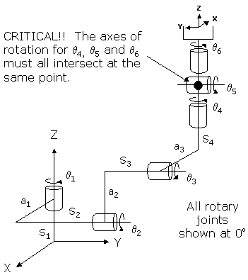
This module controls a 5-Axis or 6-Axis robot that consists of all rotary actuators. This configuration is commonly referred to as an "Articulated" robot. The first axis rotates the robot about the World Z-axis. The next two axes rotate the inner and outer links about horizontal axes. The combination of the first three axes position the wrist at a desired X, Y, Z location. The final three rotary wrist axes control the orientation of the tool flange relative to the orientation defined by the first three axes. If the robot is only configured with 5-axes, the fourth axis in the 6-axis configuration is not included.
This articulated geometry is widely used for robots that require all 6 degrees-of-freedom to move to arbitrary positions with the full range of orientation. These 6-axis robots perform a wide range of applications including parts handling, parts assembly and welding. The 5-axis configuration is most useful in applications where part insertions are primary in the vertical direction.
Kinematics Module Number and Required Software License
Module number to be entered into the "Robot type" (DataID 116): 15
Required software kinematic license (entered using the web interface panel Utilities > Controller Options if not already installed): Complex Kinematics.
Kinematic Model
| Axis | Optional | Max Range | Description |
|---|---|---|---|
|
1: q1 |
No |
+/- 359.9° |
Rotary axis that rotates the robot about the World Z-axis. A positive change in the axis angle results in a positive rotation about the World Z-axis. The center of this axis' travel can be arbitrarily set, although it is typically centered about 0, 180 or -180 degrees. |
|
2: q2 |
No |
+/- 359.9° |
Rotary axis that rotates the links of the robot about a horizontal axis. When q1 is zero, a positive change in the axis angle results in a positive rotation about the direction of the World Y-axis. The center of this axis' travel can be arbitrarily set, e.g. 0 or 45 or 180 or -135 degrees. |
|
3: q3 |
No |
+/- 359.9° |
Rotary axis that rotates the outer link about a horizontal axis. When q1 is zero, a positive change in the axis angle results in a positive rotation about the direction of the World Y-axis. The center of this axis' travel can be arbitrarily set, e.g. 0 or 45 or 180 or -135 degrees. |
|
4: q4 |
Yes |
+/- 359.9° |
Rotary axis that rotates the wrist about the outer link of the robot. When all of the axes are at their 0 positions, a positive change in this axis angle results in a positive rotation about the direction of the World Z-axis. The center of this axis' travel can be arbitrarily set, e.g. 0 or 45 or 180 or -135 degrees. This axis is not present in the 5-axis configuration. |
|
5: q5 |
No |
+/- 359.9° but typically set to +/- 179.9° |
Rotary axis that pitches the Tool orientation relative to the outer link of the robot. When all of the axes are at their 0 positions, a positive change in this axis angle results in a positive rotation about the direction of the World Y-axis. The center of this axis' travel can be arbitrarily set, e.g. 0 or 45 or 180 or -135 degrees. |
|
6: q6 |
No |
Unlimited but typically set to +/- 359.9° |
Rotary axis that rotates the end-effector about the Tool Z-axis. A positive change in the axis angle results in a positive rotation about the Tool Z-axis. The center of this axis' travel can be arbitrarily set, although it is typically centered about 0, 180 or -180 degrees. |
Parameter Database Values
The following table describes the Parameter Database values that are utilized to configure the kinematic module. Standard motion control parameters such as servo tuning values, limit stops, the homing specification, etc are not included in the table.
| Parameter Database ID | Parameter Name | Description |
|---|---|---|
|
2000 |
Number of axes |
Must be set to 5 or 6. |
|
2001 |
Split-axis mask |
Not applicable. |
|
2003 |
Axis mask |
Not applicable. |
|
2005 |
Motor linearity compensation |
Not supported. |
|
2006 |
Robot type special option flags |
Not applicable. |
|
2701 / 2703 |
100% Cartesian speeds and accels |
Value 1: Cartesian 100% linear speed and acceleration of the robot's end-effector measured along any vector in X, Y and Z. |
|
Value 2: Cartesian 100% rotation speed and acceleration of the Tool orientation about the Tool Z-axis. This is normally set to be equal to the joint control values for the 6th axis. |
||
|
Value 3: Cartesian 100% rotation speed and acceleration of the Tool's yaw and pitch orientation. This is normally set to the lesser of the joint control values for the 4th and 5th axes. |
||
|
Values 4-n: Not used. |
||
|
16050 |
Kinematic dimensional constants |
Value 1 (S1): Vertical (Z) offset from the Z=0 plane of the World coordinate system to the height of the axis of rotation of the second rotary axis (q2). Can be arbitrary set by the robot designer to establish the base of the World coordinate system. |
|
Value 2 (a1): Horizontal offset of the second axis of rotation (q2) relative to the first axis of rotation (q1) measured in a World Z plane. This is the shortest distance between the first and second axes of rotation of the robot. |
||
|
Value 3 (S2+S3): Sum of the horizontal offsets of the second (q2) and third (q3) axes. When all axes are at their 0 positions, this is the horizontal distance from a1 to a3. |
||
|
Value 4 (a2): Length of the inner link measured from the axis of q2 to that of q3. |
||
|
Value 5 (a3): Offset of the axis of rotation of q3 relative to the center line of the outer link. This is the shortest distance from the axis of rotation of q3 to the axis of rotation of q4. |
||
|
Value 6 (S4): Length of the outer link measured from the intersection of a3 and S4 to the center of the wrist, e.g. the intersection of the q4, q5 and q6 axes of rotation. NOTE: Any offset from the center of the wrist to the Tool mounting flange or gripper must be specified as part of the robot's Tool property. |
||
|
Values 7-n: Not used. |
||
|
16051 |
Tool set at restart |
When the controller is restarted, this specifies the initial value for the position and orientation of the robot's tool center point relative to the intersection of the wrist joints, q4, q5 and q6. For most simple tools, only the length of the tool needs to be defined by setting this parameter to: 0, 0, tool_length, 0, 0, 0. NOTE: Any offset from the center of the wrist to the Tool mounting flange or gripper must be specified as part of the "tool_length" value. |
|
16052 |
Base set at restart |
When the controller is restarted, this defines how the base of the robot is positioned relative to the World coordinate system. Normally, this parameter is set to 0, 0, 0, 0, 0, 0. |
Robot Configuration ("Config") Parameters
This kinematic module makes use of the following Location Config property flags to control how Cartesian positions and orientations are converted to joint angles since multiple sets of joint angles are possible:
GPL_Righty, GPL_Lefty, GPL_Above, GPL_Below, GPL_Flip, GPL_NoFlip, GPL_Single.
Special Compensation
This kinematic module does support "Continuous Turn Axes" for the the last rotary axis: q6.
This kinematic module does support "Motor Coupling" to compensate for mechanical coupling that may exist between the axes. For both the 5 and 6-axis configurations, the first motor is uncoupled and the second and third motors are coupled by a 2x2 matrix. For the 5-axis configuration, the fourth and fifth motors are coupled by a second 2x2 matrix. For the 6-axis configuration, the fourth, fifth and six motors are coupled by a 3x3 matrix.
This kinematic module does not support "Linearity Compensation" or "Split-Axis Control".
This kinematic module does support a subset of the full "Dynamic Feedforward" compensation (DFF). For this robot, the DFF compensation initially only provided position independent gravity compensation and did not generate feedforward terms to counteract dynamic effects due to accelerations and velocities. However, starting with GPL 4.1E7 and later, acceleration and velocity feedforward compensation for axes 1-3 was added.
The following diagram and table illustrate how the DFF constants are defined for this robot.
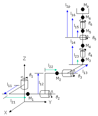
Parameter Database ID Parameter Name Values 16066
Dynamic feedforward enable
1
16067
Dynamic feedforward mass, kg
M1, M2, M3, M4, M5, M6, Mp
16068
Dynamic feedforward COM l1, mm
l11, l12, l13, l14, l15, l16, l1p
16069
Dynamic feedforward COM l2, mm
l21, l22, l23, 0, 0, 0, 0
16070
Dynamic feedforward rated torque, N-m
<filled in based on axis drives>
16071
Dynamic feedforward default %payload
Any value from 0 to 100
16072
Dynamic feedforward motor/gear inertia, kg-mm^2
Not utilized
Mp and l1p define the maximum mass of the payload and the position of this mass relative to the pitch axis. M6 and l16 represent both the tool mounting flange and the tool. If the robot only has 5-axes, M4 and l14 should be set to zero.
Additional Considerations
This kinematic module does not utilize the Custom Kinematic Parameters accessed by Robot.Custom.
This kinematic module does not have any extra, independent axes so Move.Extra has no affect.