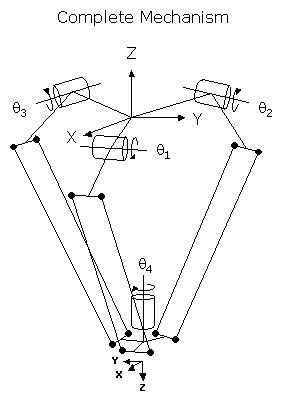
This module controls a 4 degree-of-freedom "Delta" parallel link mechanism that translates its tool platform in a fixed orientation with respect to the World X, Y, and Z axes. That is, the tool of this robot moves in the same manner as the tool of an XYZTheta Cartesian robot. The tool can translate in all three dimensions but can only be rotated about the world Z axis. This mechanism has the advantage of being extremely fast for light payloads. Some models can achieve 120 pick-and-place operations per minute or even more. Since the three primary motors are fixed, only light weight rods are moved to position the tool platform. The disadvantage of this geometry is that the working volume has very little height and has a very flat, elliptical cross section.
To move the tool platform, the three primary motors are rotated about their axes. Each motor drives a link that moves a pair of rods up and down. Each rod has a ball joint at each of its ends. The bottom ends of the 6 rods are connected to the tool platform. The combination of the three motor positions dictates the X, Y, and Z position of the center of the tool platform. A fourth, optional theta axis rotates the tool about the World Z axis.
This configuration is very popular in the packaging industry where high speed pick-and-place operations are critical and payloads are very light. Typical applications include packaging cookies and cosmetic products.
Kinematics Module Number and Required Software License
Module number to be entered into the "Robot type" (DataID 116): 6
Required software kinematic license (entered using the web interface panel Utilities > Controller Options if not already installed): Complex Kinematics.
Kinematic Model
| Axis | Optional | Max Range | Description |
|---|---|---|---|
|
1: q1 |
No |
Approximately |
Three identical rotary axes that drive links connected to vertical rods that are attached to the tool platform. Each axis has a pair of vertical rods and each rod has a ball joint at both ends. A positive change in an axis moves its corresponding link and rods lower. The zero position of each axis is at the angle where the center of the top ball joint is at the same height as the center line of the motor. The travel of each axis is limited due to mechanical "lock-up" positions in the mechanism. The exact limit on the travel is a function of the link lengths. |
|
2: q2 |
No |
||
|
3: q3 |
No |
||
|
4: q4 |
Yes |
Unlimited but typically set to +/-359.9° |
Rotary axis that rotates the end-effector about the Z-axis of the robot. A positive change in the axis angle results in a negative rotation about the World Z-axis. The center of this axis' travel can be arbitrarily set, although it is typically centered about 0, 180 or -180 degrees. |
Parameter Database Values
The following table describes the Parameter Database values that are utilized to configure the kinematic module. Standard motion control parameters such as servo tuning values, limit stops, the homing specification, etc are not included in the table.
Parameter Database ID Parameter Name Description 2000
Number of axes
Must be set to 3 or 4.
2001
Split-axis mask
Not applicable.
2003
Axis mask
Not applicable.
2005
Motor linearity compensation
Not supported.
2006
Robot type special option flags
Not applicable.
2701 / 2703
100% Cartesian speeds and accels
Value 1: Cartesian 100% linear speed and acceleration of the robot's end-effector measured along any vector in X, Y and Z.
Value 2: Cartesian 100% rotational speed and acceleration of robot's end-effector. Normally set equal to the 100% joint speed and acceleration of the theta axis.
Values 3-n: Not used.
16050
Kinematic dimensional constants
Value 1 (S0): Vertical (Z) offset of the center of the circle formed by the three motors, relative to the origin of the World coordinate system. This value can be arbitrary set by the robot designer to establish the height of the World coordinate system relative to the top of the robot.
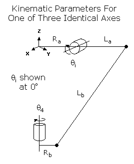
Value 2 (Ra): Radius of the circle defined by the three motors.
Value 3 (Rb): Distance from the center of the tool mounting plate to the line between the lower ball joints of any of the three pairs of vertical rods.
Value 4 (La): Length of the link that connects one of the motors to its vertical rods, measured from the axis of the motor to a ball joint of the vertical rods.
Value 5 (Lb): Length of the vertical rods measured from the top ball joint to the bottom ball joint.
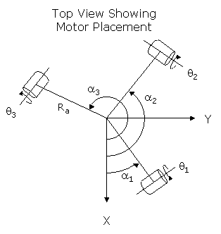
Value 6 (a1): Rotational placement of the first (q1) motor relative to the World X-axis. This angle is normally 0°.
Value 7 (a2): Rotational placement of the second (q2) motor relative to the World X-axis. This angle is normally 120°.
Value 8 (a3): Rotational placement of the third (q3) motor relative to the World X-axis. This angle is normally 240°.
Value 9: Set to 0 for compatibility with future enhancements.
Values 10-n: Not used.
16051
Tool set at restart
When the controller is restarted, this specifies the initial value for the position and orientation of the robot's tool center point relative to the tool mounting plate and the theta axis, q4. For most simple tools, only the length of the tool needs to be defined by setting this parameter to: 0, 0, tool_length, 0, 0, 0.
16052
Base set at restart
When the controller is restarted, this defines how the base of the robot is positioned and oriented relative to the World coordinate system. Normally, this parameter is set to 0, 0, 0, 0, 0, 0.
Robot Configuration ("Config") Parameters
This kinematic module makes use of the following Location Config property flags to control how Cartesian positions and orientations are converted to joint angles:
GPL_Single.
Special Compensation
This kinematic module does support "Continuous Turn Axes" for the the rotary axis: q4.
This kinematic module does not support "Motor Coupling", "Linearity Compensation" or "Split-Axis Control".
This kinematic module does not support "Dynamic Feedforward" compensation (DFF).
Additional Considerations
This kinematic module does not utilize the Custom Kinematic Parameters accessed by Robot.Custom.
This kinematic module does not have any extra, independent axes so Move.Extra has no affect.