This module controls an X/Y/Z/Theta mechanism that consists of 3 orthogonal linear axes followed by a rotary theta axis followed by an optional "Extra" independent axis. This module can be optionally configured to be used with any combination of 1 to 5 axes. For example, this module can control a single X-axis, a Y and Z mechanism, an XYZ table, a Z & theta device or a full 4 degree-of-freedom gantry robot with a servo gripper.
This module is an enhanced version of the standard XYZTheta kinematic module. In addition to all of the functionality provided by the standard module, this module supports the following special features:
-
Split-axis control. This
optionally permits pairs of motors to drive the X, Y, and Z axes
of the mechanism. For example, in gantry mechanisms,
using a X-axis motor at each end of the Y-beam can minimize the
X-axis position error between the two ends of the beam and prevent
binding.
-
Motor coupling. This
permits errors in the perpendicularity between the X, Y, and Z
axes to be compensated for in software. For example,
normally, a single scale factor is used to convert a Y-axis position
command to a motor command. But, if the Y-axis is not
perpendicular to the X-axis, as the Y-axis moves, it introduces
a small error in the X-axis position of the tool. A coupling matrix
permits Y-axis motions to automatically move the X-axis motor
to correct for this error. The motor coupling matrix
can also be applied to robot's that utilize differential drives
to move the X, Y and Z axes, such as in an "H-bot" design.
-
Motor non-linearity compensation. This
permits repeatable, non-linear motor position errors to be corrected. For
example, in some robots, a plastic encoder strip is used as the
position feedback device for a linear axis. If these
strips are glued down, sections can be slightly stretched or compressed. The
motor non-linearity compensation permits arrays of position correction
values to be entered that are automatically utilized to correct
commanded and read motor positions.
- "Extra" independent axis. This module
can be optionally configured to control an extra independent axis. This
axis does not factor into the computation of the Cartesian (XYZ)
position of the robot, but its motion can be synchronized with
the motion of the primary axes. For example, this independent
axis can control a servo gripper.
-
Dynamic Feedforward compensation
(DFF). Although this geometry typically does not
have dynamic coupling between the axes and is not subject to the
effects of centripetal and Coriolis forces (which are significant
in SCARA robots), it can have significant variation in the Z-axis
gravity loading and the effective inertia seen by each of the
axes due to changes in the payload. The Payload instruction can
be used with DFF to compensate for these variations.
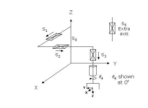
The first 3 axes of this module are linear and move the robot in X, Y, and Z. The fourth axis is rotary and turns the end-effector about the negative World Z direction. The fifth axis is an extra independent axis and is typically linear.
Kinematics Module Number and Required Software License
Module number to be entered into the "Robot type" (DataID 116): 9
Required software kinematic license (entered using the web interface panel Utilities > Controller Options if not already installed): Advanced Kinematics.
Kinematic Model
Axis Optional Max Range Description 1: S1
Yes
Max double precision range
Linear axis that moves the robot in the direction of the World X-axis. A positive change in the axis position results in a movement in the direction of the positive World X-axis.
2: S2
Yes
Max double precision range
Linear axis that moves the robot in the direction of the World Y-axis. A positive change in the axis position results in a movement in the direction of the positive World Y-axis.
3: S3
Yes
Max double precision range
Linear axis that moves the robot in the direction of the World Z-axis. A positive change in the axis position results in a movement in the direction of the negative World Z-axis.
4: q4
Yes
Unlimited but typically set to +/- 359.9°
Rotary axis that rotates the end-effector about the Z-axis of the robot. A positive change in the axis angle results in a negative rotation about the World Z-axis. The center of this axis' travel can be arbitrarily set, although it is typically centered about 0, 180 or -180 degrees.
5: S5
Yes
Unlimited
Optional independent (Extra) axis.
Parameter Database Values
The following table describes the Parameter Database values that are utilized to configure the kinematic module. Standard motion control parameters such as servo tuning values, limit stops, the homing specification, etc are not included in the table.
Parameter Database ID Parameter Name Description 2000
Number of axes
Can be set from 1 to 5.
2001
Split-axis mask
Bit mask that indicates any axes that are to be enabled as split-axes. A value of 1 indicates the X-axis, a value of 2 indicates the Y-axis, a value of 4 indicates the Z-axis, a value of 5 indicates the X and Z axes, etc. (Prior to GPL 3.2, only the X-X' axes of the Enhanced XYZTheta kinematic module supported split-axis and DataID 2001 was a Boolean value.)
2003
Axis mask
Bit mask indicating the specific axes that are to be controlled. The least significant bit (1) corresponds to the X axis. For example, if the XYZT axes are to be controlled, this value should be set to 15 (binary 01111). If only the X and Z axes are configured, this value should be set to 5 (binary 00101). If all 5 axes are to be controller, this value should be set to 31 (binary 11111).
2005
Motor linearity compensation
Set TRUE to enable motor linearity compensation. The Robot.DefLinComp method must then be executed to define the tables of compensation values.
2006
Robot type special option flags
Not applicable.
2701 / 2703
100% Cartesian speeds and accels
Value 1: Cartesian 100% linear speed and acceleration of the robot's end-effector measured along any vector in X, Y and Z.
Value 2: If the Theta axis is configured, this is the Cartesian 100% rotational speed and acceleration of the robot's end-effector. Normally set equal to the 100% joint speed and acceleration of the theta axis. If the Theta axis is not configured, but the Extra axis is configured, these are normally set equal to the 100% joint speed and acceleration of the Extra axis.
Values 3: If both the Theta and Extra axis are configured, these are normally set equal to the 100% joint speed and acceleration of the Extra axis.
Values 4-n: Not used.
16050
Kinematic dimensional constants
Value 1 (S0): Z offset for the base of the robot. Increasing this value logically moves the robot up in Z. For example, if this value is 0, when the Z-axis is at its 0 position, the tool tip will be at a World Z value of 0. Alternately, if this parameter is 100, when the Z-axis is at its 0 position, the tool tip will be at a World Z value of 100 millimeters.
Values 2-n: Not used.
16051
Tool set at restart
When the controller is restarted, this specifies the initial value for the position and orientation of the robot's tool center point relative to the end of the Z-axis. For most simple tools, only the length of the tool needs to be defined by setting this parameter to: 0, 0, tool_length, 0, 0, 0.
16052
Base set at restart
When the controller is restarted, this defines how the base of the robot is positioned and oriented relative to the World coordinate system. Normally, this parameter is set to 0, 0, 0, 0, 0, 0.
Robot Configuration ("Config") Parameters
This kinematic module makes use of the following Location Config property flags to control how Cartesian positions and orientations are converted to joint angles:
GPL_Single
Special Compensation
This kinematic module supports "Split-axis" control on the X, Y, and Z axes, and "Linearity Compensation" on all motors. Please see the "Controller Software > Software Setup > Selected Setup Details" section of the PreciseFlex™PreciseFlex Library for more information on these special modes of operation.
This module also supports "Motor coupling" between the X, Y, and Z axes. The following describes how motor conversion factors must be defined within the "Joint to motor scale factors" (DataID 2300) and the order in which they must be defined.
- If only one of the X, Y or Z axes are configured, a single scaling factor must be defined.
- If any two of the X, Y or Z axes are configured, a 2-by-2 coupling matrix specifies the joint to motor conversion between the two axes and the two motors.
- If all three of the X, Y, and Z axes are configured, a 3-by-3 coupling matrix specifies the joint to motor conversion between the three axes and the three motors.
- If the theta axis is configured, a single scale factor must be defined.
- If the extra independent axis is configured, a single scale factor must be defined.
- If Split-axis control is configured, an extra scale factor must be added for each Split-axis. The first added factor is for the first Split-axis. The scale factors for the extra motors are defined differently than the primary scale factors. The primary scale factors convert from millimeters to encoder counts. The scale factors for the extra motors convert from encoder counts of the primary motors in the split axis pairs to encoder counts for the extra motors. For example, if a primary motor moves 100 encoder counts per mm and the extra motor moves 200 encoder counts per mm, the scale factor for the primary motor will be 100 and the scale factor for the extra motor will be 2. As a special case, for backwards compatibility, if the robot only has X configured as a split-axis, the scale factor for the extra axis must be defined as encoder counts per millimeters.This kinematic module does support "Continuous Turn Axes" for the the rotary axis: q4.
This kinematic module does support "Dynamic Feedforward" compensation (DFF). This can compensate for changes in the inertia seen by each axis and the Z-axis gravity loading that are the result of changes in the robot's payload (see the Robot.Payload property).
The following diagram and table illustrate how the DFF constants are defined for this robot. For axes that are not configured, the unnecessary values in the table should be left out rather than putting in a zero or blank value.
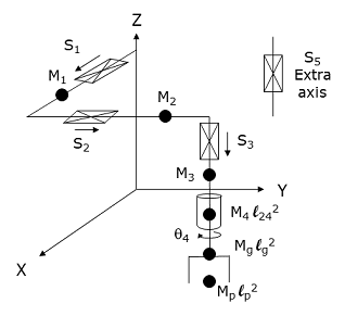
Parameter Database ID Parameter Name Values 16066
Dynamic feedforward enable
1
16067
Dynamic feedforward mass, kg
M1, M2, M3, M4, Mg, Mp
16068
Dynamic feedforward COM l1, mm
0, 0, 0, 0, 0, 0
16069
Dynamic feedforward COM l2, mm
0, 0, 0, l24, lg, lp
16070
Dynamic feedforward rated torque, N-m
<filled in based on axis drives>
16071
Dynamic feedforward default %payload
Any value from 0 to 100
16072
Dynamic feedforward motor/gear inertia, kg-mm^2
Motor and gear box inertias as seen by the axes
Mg and lg define the mass and 2nd moment of inertia for the gripper. Mp and lp define the maximum mass and 2nd moment of inertia of the payload. These maximums are reduced by the Robot.Payload property to reflect the actual payload that is in effect.
Additional Considerations
This kinematic module does not utilize the Custom Kinematic Parameters accessed by Robot.Custom.
To move the extra (5th) axis during the next motion of the primary axes to a Cartesian Location, execute the Move.Extra method. If this method is not invoked and the next motion is to a Cartesian Location, the position of the extra axis will not be altered. The following illustrates the use of Move.Extra.
Move.Extra(30)      ' Move extra axis to 30mm during next motion
Move.Loc(Location.XYZValue(300,0,100),pf1) ' Move primary and extra axis
Both the primary and the extra axes can also be simultaneously moved by performing a motion to an Angles Location. The value of this location will explicitly define the final position for all axes.