1.
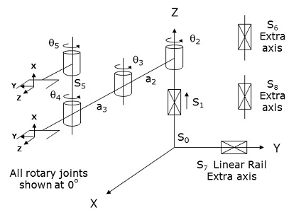
This module controls a 4, 5, 6, 7 or 8-Axis Single or Dual Yaw (PRRR) mechanism that is an enhanced variation of the standard RPRR kinematic module. This module consists of a inner link that rotates about and moves up and down in Z, connected to an outer link that rotates about a Z elbow joint, which in turn is connected to one or two wrist joints that also rotate about Z. The rotary axes position and orient the robot's end-effector(s) in the X-Y plane and produce a Yaw motion.
This module can be optionally configured to control an "Extra" independent motor (axis #6). This axis does not factor into the computation of the Cartesian (XYZ) position of the robot, but its motion can be synchronized with the motion of the primary axes. For example, this independent axis can control a servo gripper or a flipper that is attached to one of the robot's yaw axes.
This module can also be optionally configured to drive an "Extra" motor (axis #7) that controls a linear traverse rail on which the robot is mounted. The movement of this axis must be independently controlled. That is, changing the Cartesian position of the robot does not automatically move the rail. However, the position of the rail does alter the World X and/or Y position of the robot in the same way that changing Robot.Base shifts the robot's position in the World X and Y coordinates. For example, in the default configuration, if you execute a Move.OneAxis or a Move.Extra instruction to change the position of the rail by 100 mm, the robot's World Y position will be changed by 100 mm even though the other axes of the robot are unchanged.
Additionally, this module can be optionally configured to control a second "Extra" independent motor (axis #8). This axis does not factor into the computation of the Cartesian (XYZ) position of the robot, but its motion can be synchronized with the motion of the primary axes. For example, this independent axis can control a second servo gripper (dual gripper configuration).
This geometry is very popular in the Semi-conductor market for handling wafers and Life Sciences for moving sample plates.
The Standard version of this module differs from the "4/5/6-Axis Single or Dual Yaw (RPRR) Module" in the following ways:
- Axes 1 & 2 reversed. The first axis of this robot produces the prismatic (linear) displacement along the Z-axis and the second axis controls the rotation about the Z.
- Motor coupling. The 4th and 5th axes OR the 2nd, 3rd and 4th axes OR the 2nd, 3rd, 4th and 5th axes can be mechanically coupled. For example, if a rotation about q2 causes q3 or q4 to also change their position, this mechanical coupling can be mathematically corrected by filling in the terms of a 3x3 scale factor and motor coupling matrix.
- Linear traverse rail. This robot can be mounted on a linear traverse rail. The motion of the linear rail can be synchronized with the motion of the robot. Also, the position of the rail shifts the X and/or the Y World coordinate position of the robot.
Below is the standard PRRR configuration.
|
1.
|
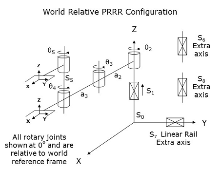
This kinematic module also supports a special "World Relative" optional configuration. When this option is enabled, in addition to the features mentioned for the Standard version, this configuration has the following attributes.
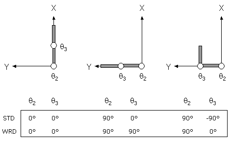
- Rotary axes relative to World Reference Frame. By convention, the angular position of a rotary joint is normally defined with respect to the orientation of its associated link. For example, if q2 is rotated by 90 degrees, the angular reading for q3 will not change even though its link has been rotated in space. However, if the "World Relative" option is enabled, the angular position of each axis is defined with respect to the World XYZ reference frame. So, if q2 is rotated by 90 degrees, the angular reading for q3 will also change by 90 degrees. The following picture illustrates the difference between the standard and World Relative interpretation of joint angles.
- Tool orientation. Normally, the Z-axis of the gripper will point along the direction in which the gripper moves to grasp an object. For the Standard form of this module, the gripper's Z-axis is always pointed in the World X/Y plane and the gripper's X-axis is pointed vertically. If the "World Relative" option is enabled, the orientations of the grippers X and Z axes are reversed.
Kinematics Module Number and Required Software License
Module number to be entered into the "Robot type" (DataID 116): 12
Required software kinematic license (entered using the web interface panel Utilities > Controller Options if not already installed): Advanced Kinematics.
Kinematic Model
| Axis | Optional | Max Range | Description |
|---|---|---|---|
|
1: S1 |
No |
Unlimited |
Linear axis that moves the robot in the direction of the World Z-axis. A positive change in the axis position results in a movement in the direction of the positive World Z-axis (up). |
|
2: q2 |
No |
Several rotations but typically set to +/- 359.9° |
Rotary axis that rotates the links of the robot about the World Z-axis. A positive change in the axis angle results in a positive rotation about the World Z-axis. The center of this axis' travel can be arbitrarily set, although it is typically centered about 0, 180 or -180 degrees. |
|
3: q3 |
No |
Several rotations but typically set to +/- 359.9° |
Rotary axis that rotates the outer link about the World Z-axis. A positive change in the axis angle results in a positive rotation about the World Z-axis. The center of this axis' travel can be arbitrarily set, although it is typically centered about 0, 180 or -180 degrees. |
|
4: q4 |
Yes |
Several rotations but typically set to +/- 359.9° |
Rotary axis that rotates the end-effector about World Z-axis. A positive change in the axis angle results in a positive rotation about the World Z-axis. The center of this axis' travel can be arbitrarily set, although it is typically centered about 0, 180 or -180 degrees. |
|
5: q5 |
Yes |
Several rotations but typically set to +/- 359.9° |
(Upper Yaw) Rotary axis that rotates the optional second end-effector about World Z-axis. A positive change in the axis angle results in a positive rotation about the World Z-axis. The center of this axis' travel can be arbitrarily set, although it is typically centered about 0, 180 or -180 degrees. |
|
6: S6 |
Yes |
Unlimited |
Optional independent (Extra) axis. |
|
7: S7 |
Yes |
Unlimited |
Optional Extra axis to control linear traverse rail. |
|
8: S8 |
Yes |
Unlimited |
Optional independent (Extra) axis. |
Parameter Database Values
The following table describes the Parameter Database values that are utilized to configure the kinematic module. Standard motion control parameters such as servo tuning values, limit stops, the homing specification, etc are not included in the table.
| Parameter Database ID | Parameter Name | Description |
|---|---|---|
|
2000 |
Number of axes |
Must be set to one of the following values: |
|
2001 |
Split-axis mask |
Not applicable. |
|
2003 |
Axis mask |
Defines the axes that are configured. Must be set to one of
the following values: |
|
2005 |
Motor linearity compensation |
Not supported. |
|
2006 |
Robot type special option flags |
Bit mask that enables special features of the kinematic module. These
bits are interpreted as follows: |
|
2701 / 2703 |
100% Cartesian speeds and accels |
Value 1: Cartesian 100% linear speed and acceleration of the robot's end-effector measured along any vector in X, Y and Z. |
|
Value 2: Cartesian 100% rotation speed and acceleration of the end-effector about the world Z-axis. |
||
|
Value 3: 100% rotation speed and acceleration of the 5th logical axis (either the upper yaw or the independent Extra axis or the linear traverse) when the primary yaw is being moved along a Cartesian straight-line path. This is normally set equal to the joint speed and acceleration of the fifth axis. |
||
|
Value 4: 100% linear speed and acceleration of the 6th logical axis (either the independent Extra axis or the linear traverse or the second independent Extra axis) when the primary yaw is being moved along a Cartesian straight-line path. This is normally set equal to the joint speed and acceleration of the sixth axis. |
||
|
Value 5: 100% linear speed and acceleration of the 7th logical axis (either the linear traverse or the second independent Extra axis) when the primary yaw is being moved along a Cartesian straight-line path. This is normally set equal to the joint speed and acceleration of the seventh axis. |
||
|
Value 6: 100% linear speed and acceleration of the 8th logical axis (the second independent Extra axis) when the primary yaw is being moved along a Cartesian straight-line path. This is normally set equal to the joint speed and acceleration of the second independent axis. |
||
|
Values 7-n: Not used. |
||
|
16050 |
Kinematic dimensional constants |
Value 1 (S0): Vertical (Z) offset of the lower Yaw axis relative to the origin of the World coordinate system when joint 1 (S1) is at its zero position. Can be arbitrary set by the robot designer to establish the height of the World coordinate system. |
|
Value 2 (a2): Length of the inner link measured from the axis of q2 to that of q3. |
||
|
Value 3 (a3): Length of the outer link measured from the axis of q3 to that of q4. |
||
|
Value 4 (S5): Vertical (Z) offset of the upper Yaw axis relative to the Z height of the lower Yaw axis. This height is automatically considered in the kinematic solution when the upper Yaw axis is selected as part of the Cartesian solution for the robot. |
||
|
Value 5 (Orientation of Linear Rail): If the optional linear rail is configured, this parameter determines how the position of the linear rail is added to the World X and/or Y coordinate of the robot. This parameter is in degrees and defines the orientation of the rail about the World Z axis. For example, if this value is 0, the position of the linear rail is added to the World Y position of the robot. If this value is -90, the position of the rail is added to the World X position of the robot. This value is normally set between -180 and +180 and defaults to 0. |
||
|
Values 6-n: Not used. |
||
|
16051 |
Tool set at restart |
When the controller is restarted, this specifies the initial value for the position and orientation of the robot's tool center point relative to the wrist joint, q4 or q5. For most simple tools, only the length of the tool needs to be defined by setting this parameter to: (0, 0, tool_length, 0, 0, 0) or (tool_length, 0, 0, 0, 0, 0) for "World Relative" configurations. |
|
16052 |
Base set at restart |
When the controller is restarted, this defines how the base of the robot is positioned and oriented relative to the World coordinate system. Normally, this parameter is set to 0, 0, 0, 0, 0, 0. |
Robot Configuration ("Config") Parameters
This kinematic module makes use of the following Location Config property flags to control how Cartesian positions and orientations are converted to joint angles since multiple sets of joint angles are possible:
GPL_Righty, GPL_Lefty, GPL_Single.
Special Compensation
This kinematic module does not support "Continuous Turn Axes" capability for any axes.
This kinematic module does support "Motor Coupling", please see above.
This kinematic module does not support "Linearity Compensation" or "Split-Axis Control".
This kinematic module does support "Dynamic Feedforward" compensation (DFF). This kinematic module includes the full DFF dynamic model for the 4-axis version of this robot. This model can compensate for the effects of coupled inertial acceleration, centripetal and Coriolis forces, and gravity loading.
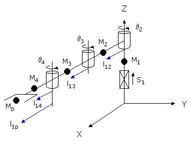
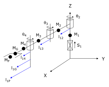
If the Enhanced DFF Model bit is not set in the "Robot type special option flags", the following diagram and table illustrate how the DFF constants are defined for this robot.
| Parameter Database ID | Parameter Name | Values |
|---|---|---|
|
16066 |
Dynamic feedforward enable |
1 |
|
16067 |
Dynamic feedforward mass, kg |
M1, M2, M3, M4, Mp |
|
16068 |
Dynamic feedforward COM l1, mm |
0, l12, l13, l14, l1p |
|
16069 |
Dynamic feedforward COM l2, mm |
0, 0, 0, 0, 0 |
|
16070 |
Dynamic feedforward rated torque, N-m |
<filled in based on axis drives> |
|
16071 |
Dynamic feedforward default %payload |
Any value from 0 to 100 |
|
16072 |
Dynamic feedforward motor/gear inertia, kg-mm^2 |
Motor and gear box inertias as seen by the axes |
Mp and l1p define the maximum mass of the payload and the position of this mass relative to the 4th axis. M4 and l14 represent both the tool mounting flange and the tool.
If the Enhanced DFF Model bit is set in the "Robot type special option flags", the following diagram and table illustrate how the DFF constants are defined for this robot.
| Parameter Database ID | Parameter Name | Values |
|---|---|---|
|
16066 |
Dynamic feedforward enable |
1 |
|
16067 |
Dynamic feedforward mass, kg |
M1, M2, M3, M4, MG, MP |
|
16068 |
Dynamic feedforward COM l1, mm |
0, l12, l13, l14, l1G, l1P |
|
16069 |
Dynamic feedforward COM l2, mm |
0, 0, 0, 0, 0 |
|
16070 |
Dynamic feedforward rated torque, N-m |
<filled in based on axis drives> |
|
16071 |
Dynamic feedforward default %payload |
Any value from 0 to 100 |
|
16072 |
Dynamic feedforward motor/gear inertia, kg-mm^2 |
Motor and gear box inertias as seen by the axes |
MG and l1G represent the mass and distance to the centroid of the tool. MP and l1P define the maximum mass of the payload and the position of this mass relative to the q4 axis. The maximum mass of the payload is dynamically reduced by the setting of the Robot.Payload instruction.
Additional Considerations
The first element of the Robot.Custom property defines which of the two yaw axes is factored into the Cartesian control of the robot (i.e. is the primary yaw axis). Specifically,
Robot.Custom(1) = 0     ' Selects the lower yaw (q4) as primary
Robot.Custom(1) = 1     ' Selects the upper yaw (q5) as primary
Whenever you modify the Robot.Custom property, execution of the thread will automatically pause until the robot has come to a stop and the change can be put into effect.
To move the secondary yaw and/or the independent Extra axis and/or the linear traverse rail and/or the second independent Extra axis during the next motion of the primary axes to a Cartesian Location, execute the Move.Extra method. If this method is not invoked and the next motion is to a Cartesian Location, the position of the secondary yaw and/or independent Extra axis and/or the linear traverse will not be altered. The following illustrates the use of Move.Extra.
Move.Extra(30)   ' Move secondary axis to 30 deg during next motion
Move.Loc(Location.XYZValue(300,0,100),pf1) ' Move primary arms tool
The yaw axes and the two independent Extra axis and the linear traverse can also be simultaneously moved by performing a motion to an Angles Location. The value of the location will explicitly define the final position for all axes.