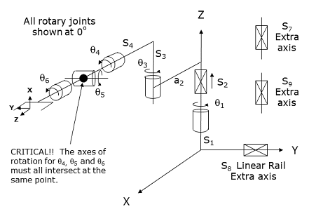
This module controls a 6-axis robot that is equivalent to a RPR robot with a 3-axis yaw-pitch-roll wrist integrated into the end of the outer link. This mechanism starts with a base Z rotation and a vertical linear axis, which rotate and translate the robot's inner link about and up and down the World Z-axis. The inner link is connected to an outer link that also rotates horizontally about a vertical axis. A 3-axis yaw-pitch-roll wrist is connected to the end of the inner link and theoretically permits the robot's gripper to achieve any desired orientation.
This kinematic configuration has the advantage of providing a large cylindrical working volume coupled with the flexibility of a 3-axis wrist. This geometry is very beneficial for both table top applications, which need small footprints while providing access to a number of instruments, as well as warehouse order picking applications, which require large vertical working volumes to access both low and high shelves while operating in narrow aisles.
This module can optionally be configured to control up to three "Extra" independent motors (axes 7, 8, 9). Axes 7 and 9 do not factor into the computation of the Cartesian (XYZ) position of the robot, but their motions can be synchronized with the motion of the primary axes. For example, these independent axes can control a servo gripper or a flipper that is attached to the robot's gripper.
The optional "Extra" axis 8 is designed to control a linear traverse rail on which the robot is mounted. The movement of this axis must be independently controlled. That is, changing the Cartesian position of the robot does not automatically move the rail. However, the position of the rail does alter the World X and/or Y position of the robot in the same way that changing Robot.Base shifts the robot's position in the World X and Y coordinates. For example, in the default configuration, if you execute a Move.OneAxis or a Move.Extra instruction to change the position of the rail by 100 mm, the robot's World Y position will be changed by 100 mm even though the other axes of the robot are unchanged.
Kinematics Module Number and Required Software License
Module number to be entered into the "Robot type" (DataID 116): 22
Required software kinematic license (entered using the web interface panel Utilities > Controller Options if not already installed): Complex Kinematics.
Kinematic Model
Axis Optional Max Range Description 1: q1
No
Several rotations but typically set to +/- 359.9°
Rotary axis that rotates the robot about the World Z-axis. A positive change in the axis angle results in a positive rotation about the World Z-axis. The center of this axis' travel can be arbitrarily set, although it is typically centered about 0, 180 or -180 degrees.
2: S2
No
Unlimited
Linear axis that moves the robot in the direction of the World Z-axis. A positive change in the axis position results in a movement in the direction of the positive World Z-axis (up).
3: q3
No
Several rotations but typically set to +/- 359.9°
Rotary axis that rotates the outer link about the World Z-axis. A positive change in the axis angle results in a positive rotation about the World Z-axis. The center of this axis' travel can be arbitrarily set, although it is typically centered about 0, 180 or -180 degrees.
4: q4
No
Several rotations but typically set to +/- 359.9°
Rotary axis that rotates the wrist about the outer link of the robot. When all of the axes are at their 0 positions, a positive change in this axis angle results in a positive rotation about the direction of the World X-axis. The center of this axis' travel can be arbitrarily set, e.g. 0 or 45 or 180 or -135 degrees.
5: q5
No
Several rotations but typically set to +/- 179.9°
Rotary axis that pitches the Tool orientation relative to the outer link of the robot. When all of the axes are at their 0 positions, a positive change in this axis angle results in a positive rotation about the direction of the World Y-axis. The center of this axis' travel can be arbitrarily set, e.g. 0 or 45 or 180 or -135 degrees.
6: q6
No
Unlimited but typically set to +/- 359.9°
Rotary axis that rotates the end-effector about the Tool Z-axis. A positive change in the axis angle results in a positive rotation about the Tool Z-axis. The center of this axis' travel can be arbitrarily set, although it is typically centered about 0, 180 or -180 degrees.
7: S7
Yes
Unlimited
Optional independent (Extra) axis.
8: S8
Yes
Unlimited
Optional Extra axis to control linear traverse rail.
9: S9
Yes
Unlimited
Optional independent (Extra) axis.
Parameter Database Values
The following table describes the Parameter Database values that are utilized to configure the kinematic module. Standard motion control parameters such as servo tuning values, limit stops, the homing specification, etc are not included in the table.
Parameter Database ID Parameter Name Description 2000
Number of axes
Must be set to one of the following values:
6: Six axis robot with no optional axes.
7: Six axis robot plus any one of the three optional axes.
8: Six axis robot plus any two of the three optional axes.
9: Six axis robot plus all three of the optional axes.2001
Split-axis mask
Not applicable.
2003
Axis mask
Defines the axes that are configured. Must be set to one of the following values:
63 (&H3f): Six axis robot.
Add 64 (&H40) for the first independent axis.
Add 128 (&H80) for the linear traverse axis.
Add 256 (&H100) for the second independent axis.2005
Motor linearity compensation
Not supported.
2006
Robot type special option flags
Not applicable.
2701 / 2703
100% Cartesian speeds and accels
Value 1: Cartesian 100% linear speed and acceleration of the robot's end-effector measured along any vector in X, Y and Z.
Value 2: Cartesian 100% rotation speed and acceleration of the Tool orientation about the Tool Z-axis. This is normally set to be equal to the joint control values for the 6th axis.
Value 3: Cartesian 100% rotation speed and acceleration of the Tool's yaw and pitch orientation. This is normally set to the lesser of the joint control values for the 4th and 5th axes.
Value 4: Should be set to 1.0 or some other non-zero value for this module to operate properly.
Value 5: 100% linear speed and acceleration of the 7th logical axis (either the first Extra axis or the linear traverse or the second independent Extra axis). This is normally set equal to the joint speed and acceleration of the 7th axis.
Value 6: 100% linear speed and acceleration of the 8th logical axis (either the linear traverse or the second independent Extra axis). This is normally set equal to the joint speed and acceleration of the 8th axis.
Value 7: 100% linear speed and acceleration of the 9th logical axis (the second independent Extra axis). This is normally set equal to the joint speed and acceleration of the 9th axis.
Values 8-n: Not used.
16050
Kinematic dimensional constants
Value 1 (S1): Vertical (Z) offset from the Z=0 plane of the World coordinate system to the zero position of vertical linear axis (S2). S1 and S2 are added to the Base Z offset to determine the vertical (Z World) position of the inner link. Can be arbitrary set by the robot designer to establish the base of the World coordinate system.
Value 2 (a2): Length of the inner link measured from the axis of q1 to that of q3.
Value 3 (S3): Vertical offset between the inner and the outer link.
Value 4 (S4): Length of the outer link measured from the axis of q3 to that of q5.
Value 5 (Orientation of Linear Rail): If the optional linear rail is configured, this parameter determines how the position of the linear rail is added to the World X and/or Y coordinate of the robot. This parameter is in degrees and defines the orientation of the rail about the World Z axis. For example, if this value is 0, the position of the linear rail is added to the World Y position of the robot. If this value is -90, the position of the rail is added to the World X position of the robot. This value is normally set between -180 and +180 and defaults to 0.
Values 6-n: Not used.
16051
Tool set at restart
When the controller is restarted, this specifies the initial value for the position and orientation of the robot's tool center point relative to the intersection of the wrist joints, q4, q5 and q6. For most simple tools, only the length of the tool needs to be defined by setting this parameter to: 0, 0, tool_length, 0, 0, 0.
NOTE: Any offset from the center of the wrist to the Tool mounting flange or gripper must be specified as part of the "tool_length" value.
16052
Base set at restart
When the controller is restarted, this defines how the base of the robot is positioned relative to the World coordinate system. Normally, this parameter is set to 0, 0, 0, 0, 0, 0.
Robot Configuration ("Config") Parameters
This kinematic module makes use of the following Location Config property flags to control how Cartesian positions and orientations are converted to joint angles since multiple sets of joint angles are possible:
GPL_Righty, GPL_Lefty, GPL_Flip, GPL_NoFlip, GPL_Single.
Special Compensation
This kinematic module does support "Continuous Turn Axes" for the the last rotary axis: q6.
This kinematic module does support "Motor Coupling" to compensate for mechanical coupling that may exist between the axes. The first motor is uncoupled and the second and third motors are coupled by a 2x2 matrix. The fourth, fifth and six motors are coupled by a 3x3 matrix.
This kinematic module does not support "Linearity Compensation" or "Split-Axis Control".
This kinematic module does support "Dynamic Feedforward" compensation (DFF). This kinematic module includes the full DFF dynamic model of this robot. This model can compensate for the effects of coupled inertial acceleration, centripetal and Coriolis forces, and gravity loading.
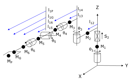
The following diagram and table illustrate how the DFF constants are defined for this robot.
Parameter Database ID Parameter Name Values 16066
Dynamic feedforward enable
1
16067
Dynamic feedforward mass, kg
M1, M2, M3, M4, M5, M6, MG, MP
16068
Dynamic feedforward COM l1, mm
0, l12, l13, l14, l15, l16, l1G, l1P
16069
Dynamic feedforward COM l2, mm
l21, 0, 0, l24, 0, l26, l2G, l2P
16070
Dynamic feedforward rated torque, N-m
<filled in based on axis drives>
16071
Dynamic feedforward default %payload
Any value from 0 to 100
16072
Dynamic feedforward motor/gear inertia, kg-mm^2
Motor and gear box inertias as seen by the axes
MG and l1G represent the mass and distance to the centroid of the tool. Mp and l1p define the maximum mass of the payload and the position of this mass relative to the pitch axis. The maximum mass of the payload is dynamically reduced by the setting of the Robot.Payload instruction. The l2? dimensions are used for computing the rotational inertias when masses are rotated about their own axis. For example, M1*l21^2 times the acceleration of q1 is added to the other computed DFF torques for the first motor.
Additional Considerations
This kinematic module does not utilize the Custom Kinematic Parameters accessed by Robot.Custom.
To move the first independent Extra axis and/or the linear traverse rail and/or the second independent Extra axis during the next motion of the primary axes to a Cartesian Location, execute the Move.Extra method. If this method is not invoked and the next motion is to a Cartesian Location, the position of any configured Extra axes will not be altered. The following illustrates the use of Move.Extra.
Move.Extra(30)   ' Move 1st Extra axis to 30 deg during next motion
Move.Loc(Location.XYZValue(300,0,100),pf1) ' Move primary arms tool
The two independent Extra axis and the linear traverse can also be simultaneously moved by performing a motion to an Angles Location. The value of the location will explicitly define the final position for all axes.