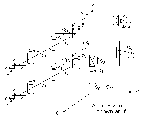
This module controls a 3-axis single arm or 4-axis dual arm RPR mechanism. This device consists of a base column that rotates about and moves up and down in Z. Mounted on this column is one or two arms. Each arm consists of an inner link, an outer link and an end-effector. The two links and end-effector are mechanically coupled such that a rotation of the inner link relative to the base column produces a linear radial motion of the end-effector without altering the orientation of the end-effector.
This module can be optionally configured to control one or two "Extra" independent axes. These axes do not factor into the computation of the Cartesian (XYZ) position of the robot, but their motions can be synchronized with the motion of the primary axes. For example, these independent axes can control linear traversal stages that move the entire robot between stations or they can control flippers that are attached to one or both of the robot's grippers.
This configuration is very popular for transferring semi-conductor wafers in tool front-end material handling systems. It is often referred to as a "Wafer Transfer Robot" (WTR) configuration.
Examining the lower arm, its movement is controlled by q3. q3' and q3" are mechanically coupled to q3, such that when q3 is rotated, the gripper moves in a linear radial motion while maintaining a fixed orientation. These three angles are related by the following equations:
q3' = -2 q3 and q3" = q3
If both arms are configured, the position and orientation of the designated "primary" arm is combined with the first two axes to compute and control the Cartesian (XYZ) location of the robot. The secondary arm does not factor into the Cartesian location of the robot and operates as an independent axis. The secondary arm can be simultaneously moved with the primary arm or can remain stationary. For example, the primary arm can be extended while the secondary arm is simultaneously retracted. The arm that is designated as the "primary" can be dynamically switched using the Robot.Custom property (see below).
Kinematics Module Number and Required Software License
Module number to be entered into the "Robot type" (DataID 116): 5
Required software kinematic license (entered using the web interface panel Utilities > Controller Options if not already installed): Advanced Kinematics.
Kinematic Model
Axis Optional Max Range Description 1: q1
No
+/- 359.9°
Rotary axis that rotates the links of the robot about the World Z-axis. A positive change in the axis angle results in a positive rotation about the World Z-axis. The center of this axis' travel can be arbitrarily set, although it is typically centered about 0, 180 or -180 degrees.
2: S2
No
Max double precision range
Linear axis that moves the robot in the direction of the World Z-axis. A positive change in the axis position results in a movement in the direction of the positive World Z-axis (up).
3: q3
No
+/- 179.9°
Rotary axis that rotates the inner link of the lower arm about the World Z-axis. A positive change in the axis angle results in a positive rotation about the World Z-axis. The center of this axis' travel can be arbitrarily set, although it is typically centered about 0, 180 or -180 degrees.
4: q4
Yes
+/- 179.9°
Optional rotary axis that rotates the inner link of the upper arm about World Z-axis. A positive change in the axis angle results in a positive rotation about the World Z-axis. The center of this axis' travel can be arbitrarily set, although it is typically centered about 0, 180 or -180 degrees.
5: S5
Yes
Unlimited
First optional independent (Extra) axis.
6: S6
Yes
Unlimited
Second optional independent (Extra) axis.
Parameter Database Values
The following table describes the Parameter Database values that are utilized to configure the kinematic module. Standard motion control parameters such as servo tuning values, limit stops, the homing specification, etc are not included in the table.
Parameter Database ID Parameter Name Description 2000
Number of axes
Must be set to one of the following values:
3: Single arm robot.
4: Dual arm or a single arm with an independent axis.
5: Dual arm with an independent axis or a single arm with two independent axes.
6: Dual arm with two independent axes.2001
Split-axis mask
Not applicable.
2003
Axis mask
Defines the axes that are configured. Must be set to one of the following values:
7 (&H07): Single arm robot.
15 (&H0f): Dual arm robot.
23 (&H17): Single arm plus independent axis.
31 (&H1f): Dual arm plus independent axis.
55 (&H37): Single arm with two independent axes.
63 (&H3F): Dual arm with two independent axes.2005
Motor linearity compensation
Not supported.
2006
Robot type special option flags
Bit mask that enables special features of the kinematic module. These bits are interpreted as follows:
2 (&H02): If set, motor coupling is enabled and for single arm robots, the coupling between motors 1/2/3 is defined by a 3x3 matrix that is stored as the first 9 elements of the "Joint to motor scale factors" (DataID 2300). For dual arm robots, the coupling between motors 1/2/3/4 is defined by a 4x4 matrix in DataID 2300. If this bit is not set, motor coupling is disabled and none of the motors are mechanically coupled.2701 / 2703
100% Cartesian speeds and accels
Value 1: Cartesian 100% linear speed and acceleration of the robot's end-effector measured along any vector in X, Y and Z.
Value 2: 100% rotation speed and acceleration of the 4th logical axis (either the second arm or the first Extra axis) when the primary arm is being moved along a Cartesian straight-line path. This is normally set equal to the joint speed and acceleration of the fourth axis.
Value 3: 100% rotation speed and acceleration of the 5th logical axis (either the first or second Extra axis) when the primary arm is being moved along a Cartesian straight-line path. This is normally set equal to the joint speed and acceleration of the first or second Extra axis.
Value 4: 100% rotation speed and acceleration of the 6th logical axis (the second Extra axis) when the primary arm is being moved along a Cartesian straight-line path. This is normally set equal to the joint speed and acceleration of the second Extra axis.
Values 5-n: Not used.
16050
Kinematic dimensional constants
Value 1 (S01): Vertical (Z) offset of the tool relative to the origin of the World coordinate system when joint 2 (S2) is at its zero position and the lower arm, which is controlled by q3, is selected as the primary arm. Can be arbitrary set by the robot designer to establish the height of the World coordinate system.
Value 2 (S02): Vertical (Z) offset of the tool relative to the origin of the World coordinate system when joint 2 (S2) is at its zero position and the upper arm, which is controlled by q4, is selected as the primary arm. Once S01 is defined, the difference between S02 and S01 should be equal to the difference in height of the upper and the lower arms.
Value 3 (dx1): Offset of the axis of q3 from the axis of S2, measured along the X direction. Typically, this value is 0.
Value 4 (dx2): Offset of the axis of q4 from the axis of S2, measured along the X direction. Typically, this value is 0.
Value 5 (dy1): Offset of the axis of q3 from the axis of S2, measured along the Y direction. Typically, this value is 0.
Value 6 (dy2): Offset of the axis of q4 from the axis of S2, measured along the Y direction. Typically, this value is 0.
Value 7 (a3): Length of the inner and outer links of both arms. All four lengths should be equal to the distance from the axis of q3 to that of q3'.
Values 8-n: Not used.
16051
Tool set at restart
When the controller is restarted, this specifies the initial value for the position and orientation of the robot's tool center point relative to the wrist joint. For most simple tools, only the length of the tool needs to be defined by setting this parameter to: 0, 0, tool_length, 0, 0, 0.
16052
Base set at restart
When the controller is restarted, this defines how the base of the robot is positioned and oriented relative to the World coordinate system. Normally, this parameter is set to 0, 0, 0, 0, 0, 0.
Robot Configuration ("Config") Parameters
This kinematic module makes use of the following Location Config property flags to control how Cartesian positions and orientations are converted to joint angles since multiple sets of joint angles are possible:
GPL_Righty, GPL_Lefty.
Special Compensation
This kinematic module does optionally support "Motor Coupling" between axes 1/2/3 or 1/2/3/4, see above.
This kinematic module does not support "Continuous Turn Axes" capability for any axes.
This kinematic module does not support "Linearity Compensation" or "Split-Axis Control".
This kinematic module does not support "Dynamic Feedforward" compensation (DFF).
Additional Considerations
The first element of the Robot.Custom property defines which of the two arms serves as the primary arm. Specifically,
Robot.Custom(1) = 0     ' Selects the lower arm (q3) as primary
Robot.Custom(1) = 1     ' Selects the upper arm (q4) as primary
Whenever you modify the Robot.Custom property, execution of the thread will automatically pause until the robot has come to a stop and the change can be put into effect.
To move the secondary arm and/or the Extra axis during the next motion of the primary axes to a Cartesian Location, execute the Move.Extra method. If this method is not invoked and the next motion is to a Cartesian Location, the position of the secondary arm and/or Extra axis will not be altered. The following illustrates the use of Move.Extra.
Move.Extra(30)   ' Move secondary axis to 30 deg during next motion
Move.Loc(Location.XYZValue(300,0,100),pf1) ' Move primary arms tool
Both arms and the Extra axes can also be simultaneously moved by performing a motion to an Angles Location. The value of the location will explicitly define the final position for all axes.