This module controls a 3-axis single arm or 4-axis dual arm RPR mechanism. This mechanism is similar to the commonly used RPR configuration, except that a coupled elbow joint is not provided. The standard RPR mechanism mechanically couples the elbow and the wrist to the shoulder axis such that a rotation of the inner link relative to the base column produces a pure linear radial motion of the end-effector and no change in the orientation of the end-effector. When the elbow joint is eliminated, a rotation of the inner link changes the radial position of the end-effector, however, the end-effector's position and orientation will also be rotated with respect to the base column.
This device consists of a base column that rotates about and moves up and down in Z. Mounted on this column is one or two arms. Each arm consists of an inner link (no outer link) and a wrist axis. The inner link and the wrist axis are mechanically coupled as described below.
This module can be optionally configured to control an "Extra" independent axis. This axis does not factor into the computation of the Cartesian (XYZ) position of the robot, but its motion can be synchronized with the motion of the primary axes. For example, this independent axis can control a linear traversal stage that moves the entire robot between stations or it can control a flipper that is attached to one of the robot's grippers.
This configuration is very useful for transferring semi-conductor wafers in tool front-end material handling systems.
For the two arms, the wrist axes are mechanically coupled to the inner link shoulder axes. Their angular positions are related by the following equations:
q3' = -1/2 q3 and q4' = -1/2 q4
If both arms are configured, the position and orientation of the designated "primary" arm is combined with the first two axes to compute and control the Cartesian (XYZ) location of the robot. The secondary arm does not factor into the Cartesian location of the robot and operates as an independent axis. The secondary arm can be simultaneously moved with the primary arm or can remain stationary. For example, the primary arm can be extended while the secondary arm is simultaneously retracted. The arm that is designated as the "primary" can be dynamically switched using the Robot.Custom property (see below).
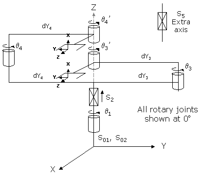
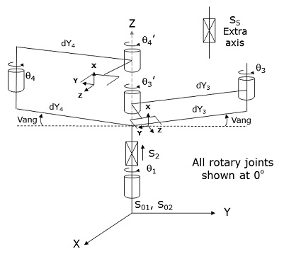
As a new option in GPL 4.1 and later, as shown below, the tangent line between the axes of rotation for the two inner links, q3 and q4, need not intersect the axis of rotation for the base column rotation, q1. When Vang is non-zero, instead of the offsets for q3 and q4 forming a straight line, they form a "V" when viewed from above. Whether Vang is zero or non-zero (for backwards compatibility), when q3 and q4 are zero, the inner links are aligned with the offsets from the base column to the axes of q3 and q4 and the wrist axes are perpendicular to the inner links.
Kinematics Module Number and Required Software License
Module number to be entered into the "Robot type" (DataID 116): 16
Required software kinematic license (entered using the web interface panel Utilities > Controller Options if not already installed): Advanced Kinematics.
Kinematic Model
Axis Optional Max Range Description 1: q1
No
+/- 359.9°
Rotary axis that rotates the links of the robot about the World Z-axis. A positive change in the axis angle results in a positive rotation about the World Z-axis. The center of this axis' travel can be arbitrarily set, although it is typically centered about 0, 180 or -180 degrees.
2: S2
No
Max double precision range
Linear axis that moves the robot in the direction of the World Z-axis. A positive change in the axis position results in a movement in the direction of the positive World Z-axis (up).
3: q3
No
+/- 179.9°
Rotary axis that rotates the inner link of the lower arm about the World Z-axis. A positive change in the axis angle results in a positive rotation about the World Z-axis. The center of this axis' travel can be arbitrarily set, although it is typically centered about 0 degrees.
4: q4
Yes
+/- 179.9°
Optional rotary axis that rotates the inner link of the upper arm about World Z-axis. A positive change in the axis angle results in a positive rotation about the World Z-axis. The center of this axis' travel can be arbitrarily set, although it is typically centered about 0 degrees.
5: S5
Yes
Unlimited
Optional independent (Extra) axis.
Parameter Database Values
The following table describes the Parameter Database values that are utilized to configure the kinematic module. Standard motion control parameters such as servo tuning values, limit stops, the homing specification, etc are not included in the table.
Parameter Database ID Parameter Name Description 2000
Number of axes
Must be set to one of the following values:
3: Single arm robot.
4: Dual arm or a single arm with an independent axis.
5: Dual arm with an independent axis.2001
Split-axis mask
Not applicable.
2003
Axis mask
Defines the axes that are configured. Must be set to one of the following values:
7 (&H07): Single arm robot.
15 (&H0f): Dual arm robot.
23 (&H17): Single arm plus independent axis.
31 (&H1f): Dual arm plus independent axis.2005
Motor linearity compensation
Not supported.
2006
Robot type special option flags
Bit mask that enables special features of the kinematic module. These bits are interpreted as follows:
&H02: If set and the robot has a single arm, the first 3 motors are coupled by a 3x3 coupling matrix. If set and the robot has a dual arm, the first 4 motors are coupled by a 4x4 coupling matrix. If not set, all of the motors are uncoupled.2701 / 2703
100% Cartesian speeds and accels
Value 1: Cartesian 100% linear speed and acceleration of the robot's end-effector measured along any vector in X, Y and Z.
Value 2: 100% rotation speed and acceleration of the 4th logical axis (either the second arm or the Extra axis) when the primary arm is being moved along a Cartesian straight-line path. This is normally set equal to the joint speed and acceleration of the fourth axis.
Value 3: 100% rotation speed and acceleration of the 5th logical axis (the Extra axis) when the primary arm is being moved along a Cartesian straight-line path. This is normally set equal to the joint speed and acceleration of the Extra axis.
Values 4-n: Not used.
16050
Kinematic dimensional constants
Value 1 (S01): Vertical (Z) offset of the tool relative to the origin of the World coordinate system when joint 2 (S2) is at its zero position and the lower arm, which is controlled by q3, is selected as the primary arm. Can be arbitrary set by the robot designer to establish the height of the World coordinate system.
Value 2 (S02): Vertical (Z) offset of the tool relative to the origin of the World coordinate system when joint 2 (S2) is at its zero position and the upper arm, which is controlled by q4, is selected as the primary arm. Once S01 is defined, the difference between S02 and S01 should be equal to the difference in height of the upper and the lower arms.
Value 3 (dy3): Horizontal offset of the axis of q3 from the axis of q1, measured along the Y direction. This value is also equal to the length of the inner link for the lower arm. As illustrated in the drawing above with q3 to the right of q1, this constant should have a positive value.
Value 4 (dy4): Horizontal offset of the axis of q4 from the axis of q1, measured along the -Y direction. This value is also equal to the length of the inner link for the upper arm. As illustrated in the drawing above with q4 to the left of q1, this constant should have a positive value.
Value 5 (Vang): Angle of rotation (in degrees) of the horizontal offset for q3 relative to its nominal orientation when the tangent from q3 to q4 intersects the axis of q1. When this value is 0, the q3 and q4 offsets are in a straight line per the kinematic drawing at the top of this section.
Values 6-n: Not used.
16051
Tool set at restart
When the controller is restarted, this specifies the initial value for the position and orientation of the robot's tool center point relative to the wrist joint. For most simple tools, only the length of the tool needs to be defined by setting this parameter to: 0, 0, tool_length, 0, 0, 0.
16052
Base set at restart
When the controller is restarted, this defines how the base of the robot is positioned and oriented relative to the World coordinate system. Normally, this parameter is set to 0, 0, 0, 0, 0, 0.
Robot Configuration ("Config") Parameters
This kinematic module makes use of the following Location Config property flags to control how Cartesian positions and orientations are converted to joint angles:
None
Special Compensation
This kinematic module does not support "Continuous Turn Axes" capability for any axes.
This kinematic module does support "Motor Coupling", please see above.
This kinematic module does not support "Linearity Compensation" or "Split-Axis Control".
This kinematic module does support "Dynamic Feedforward" compensation (DFF). This kinematic module includes the full DFF dynamic model for the 3-axis single arm version of this robot but initially did not support the 4-axis dual arm version. Starting with GPL 4.1E7, support for the second arm (axis 4) was added. This model can compensate for the effects of coupled inertial acceleration, centripetal and Coriolis forces, and gravity loading.
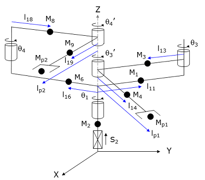
The following diagram and table illustrate how the DFF constants are defined for this robot.
Parameter Database ID Parameter Name Values 16066
Dynamic feedforward enable
1
16067
Dynamic feedforward mass, kg
M1, M2, M3, M4, Mp1, M6, 0, M8, M9, Mp2
16068
Dynamic feedforward COM l1, mm
l11, 0, l13, l14, lp1, l16, 0, l18, l19, lp2
16069
Dynamic feedforward COM l2, mm
0, 0, 0, 0, 0
16070
Dynamic feedforward rated torque, N-m
<filled in based on axis drives>
16071
Dynamic feedforward default %payload
Any value from 0 to 100
16072
Dynamic feedforward motor/gear inertia, kg-mm^2
Motor and gear box inertias as seen by the axes
Mp1 and lp1 define the maximum mass of the payload and the position of this mass relative to the 3th axis, q3'. M4 and l14 represent both the tool mounting flange and the tool for the 3rd axis. Likewise, Mp2, lp2, M9 and l19 apply to the 4th axis.
Note, this robot module is kinematically defined with the first axis as a rotation, q1, and the second as the Z-axis, S2. However, mechanically, the q1 drive mechanism is typically mounted on the Z-axis and goes up and down with the Z. Therefore, in the DFF dynamic model, the Z-axis is positioned below q1and the mass of q1 is lifted by the Z-axis.
Additional Considerations
The first element of the Robot.Custom property defines which of the two arms serves as the primary arm. Specifically,
Robot.Custom(1) = 0     ' Selects the lower arm (q3) as primary
Robot.Custom(1) = 1     ' Selects the upper arm (q4) as primary
Whenever you modify the Robot.Custom property, execution of the thread will automatically pause until the robot has come to a stop and the change can be put into effect.
To move the secondary arm and/or the Extra axis during the next motion of the primary axes to a Cartesian Location, execute the Move.Extra method. If this method is not invoked and the next motion is to a Cartesian Location, the position of the secondary arm and/or Extra axis will not be altered. The following illustrates the use of Move.Extra.
Move.Extra(30)   ' Move secondary axis to 30 deg during next motion
Move.Loc(Location.XYZValue(300,0,100),pf1) ' Move primary arms tool
Both arms and the Extra axis can also be simultaneously moved by performing a motion to an Angles Location. The value of the location will explicitly define the final position for all axes.