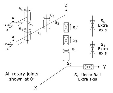
This module controls a 4 or 5-Axis Single or Dual Yaw (RPRR) mechanism that consists of a inner link that rotates about and moves up and down in Z, connected to an outer link that rotates about a Z elbow joint, which in turn is connected to one or two wrist joints that also rotate about Z. The rotary axes position and orient the robot's end-effector(s) in the X-Y plane and produce a Yaw motion.
This module can be optionally configured to control an "Extra" independent axis. This axis does not factor into the computation of the Cartesian (XYZ) position of the robot, but its motion can be synchronized with the motion of the primary axes. For example, this independent axis can control a servo gripper or a flipper that is attached to one of the robot's yaw axes.
This module can also be optionally configured to drive an "Extra" motor (axis #7) that controls a linear traverse rail on which the robot is mounted. The movement of this axis must be independently controlled. That is, changing the Cartesian position of the robot does not automatically move the rail. However, the position of the rail does alter the World X and/or Y position of the robot in the same way that changing Robot.Base shifts the robot's position in the World X and Y coordinates. For example, in the default configuration, if you execute a Move.OneAxis or a Move.Extra instruction to change the position of the rail by 100 mm, the robot's World Y position will be changed by 100 mm even though the other axes of the robot are unchanged.
Additionally, this module can be optionally configured to control a second "Extra" independent motor (axis #8). This axis does not factor into the computation of the Cartesian (XYZ) position of the robot, but its motion can be synchronized with the motion of the primary axes. For example, this independent axis can control a second servo gripper (dual gripper configuration).
This robot configuration is very popular in both the Life Sciences and Semi-conductor markets to horizontally load and unload products into other equipment.
If both yaws are configured, the orientation of the designated "primary" yaw is combined with the first three axes to compute and control the Cartesian (XYZ) location and orientation of the robot. The secondary yaw does not factor into the Cartesian location and orientation of the robot and operates as an independent axis. The secondary yaw can be simultaneously moved with the primary yaw or can remain stationary. For example, the arm can be extended while the secondary yaw is simultaneously folded back. The yaw that is designated as the "primary" can be dynamically switched using the Robot.Custom property (see below).
In GPL 4.3 and later, the vertical axis can be optionally driven by a two-stage telescoping pair of actuators, S2 and S2', that are electronically coupled to automatically and synchronously move together. From an application programming point of view, these telescoping stages operate as a single logical Z-axis. From a configuration point of view, these coupled actuators must be tuned and setup using the system's "Split-Axis Control" capability. The split-axis control permits the system to keep these coupled axis in alignment.
Several characteristics of the Split-Axis control must be kept in mind:
- By convention, the coupled motor for the Split-axis pair will
be the 5th motor for a single Yaw system and the 6th motor for a dual Yaw system.
- It is highly recommended that absolute encoders be used for all coupled motors
since this greatly simplifies homing and commutation reference finding.
- When the robot is homed and during each subsequent time that motor power
is enabled, the system will automatically move coupled axes
slowly into alignment. The motor speed during the alignment process is controlled
by the "Homing speed 1" (DataID 2804).
- If the optional telescoping Z-axis is configured, the "Joint to motor
scale factors" (DataID 2300) for the coupled S2' motor
is typically set to 1 to indicate that the travel and scale factor for both
stages are identical. If the travel and scale factors for the two stages are
different, the "Joint to motor scale factor" for S2' should
be adjusted appropriately. The "Joint
to motor scale factor" for
the S2 motor
should be set to represent the full motion generated by the combination of
the two coupled axes. That is, if each of the two motors moves the Z-axis 1
mm for every 1000 encoder counts, the scale factor for S2 should
be set to 2000.
- Manual control "Free" mode is not permitted for any split axes since Split-axis
control does not operate in Free mode and split axes re-alignment is not performed
when Free mode is terminated.
Kinematics Module Number and Required Software License
Module number to be entered into the "Robot type" (DataID 116): 4
Required software kinematic license (entered using the web interface panel Utilities > Controller Options if not already installed): Advanced Kinematics.
Kinematic Model
Axis Optional Max Range Description 1: q1
No
Unlimited but typically set to +/- 359.9°
Rotary axis that rotates the links of the robot about the World Z-axis. A positive change in the axis angle results in a positive rotation about the World Z-axis. The center of this axis' travel can be arbitrarily set, although it is typically centered about 0, 180 or -180 degrees.
2: S2
No
Unlimited
Linear axis that moves the robot in the direction of the World Z-axis. A positive change in the axis position results in a movement in the direction of the positive World Z-axis (up).
3: q3
No
Unlimited but typically set to +/- 179.9°
Rotary axis that rotates the outer link about the World Z-axis. A positive change in the axis angle results in a positive rotation about the World Z-axis. The center of this axis' travel can be arbitrarily set, although it is typically centered about 0, 180 or -180 degrees.
4: q4
No
Unlimited but typically set to +/- 359.9°
Rotary axis that rotates the end-effector about World Z-axis. A positive change in the axis angle results in a positive rotation about the World Z-axis. The center of this axis' travel can be arbitrarily set, although it is typically centered about 0, 180 or -180 degrees.
5: q5
Yes
Unlimited but typically set to +/- 359.9°
(Upper Yaw) Rotary axis that rotates the optional second end-effector about World Z-axis. A positive change in the axis angle results in a positive rotation about the World Z-axis. The center of this axis' travel can be arbitrarily set, although it is typically centered about 0, 180 or -180 degrees.
6: S6
Yes
Unlimited
Optional independent (Extra) axis.
7: S7
Yes
Unlimited
Optional Extra axis to control linear traverse rail.
8: S8
Yes
Unlimited
Optional independent (Extra) axis.
Parameter Database Values
The following table describes the Parameter Database values that are utilized to configure the kinematic module. Standard motion control parameters such as servo tuning values, limit stops, the homing specification, etc are not included in the table.
Parameter Database ID Parameter Name Description 2000
Number of axes
Must be set to one of the following values:
4: Single Yaw robot.
5: Dual Yaw OR a single Yaw with an independent axis OR single Yaw with a linear traverse rail.
6: Dual Yaw with an independent axis OR a Dual Yaw with a linear traverse rail OR a single Yaw with an independent axis and a linear traverse rail OR a single Yaw with two independent axes.
7: Dual Yaw with an independent axis and a linear traverse rail OR a Dual Yaw with two independent axes OR a single Yaw with two independent axes and a linear traverse rail.
8: Dual Yaw with two independent axes and a linear traverse rail.2001
Split-axis mask
To enable the optional telescoping Z-axis configuration, this value must be set to 2.
2003
Axis mask
Defines the axes that are configured. Must be set to one of the following values:
15 (&H0f): Single Yaw robot.
31 (&H1f): Dual Yaw robot.
Add 32 (&H20) for the first independent axis.
Add 64 (&H40) for the linear traverse axis.
Add 128 (&H80) for the second independent axis.2005
Motor linearity compensation
Not supported.
2006
Robot type special option flags
Bit mask that enables special features of the kinematic module. These bits are interpreted as follows:
256 (&H100): If set, enables the Enhanced Dynamic Feedforward (DFF) model. For this module, the enhanced model includes separate specifications for the gripper and payload, and an explicit definition for the rotational inertia of the Z-axis mass about its axis.2300
Joint to motor scale factors
When the robot is configured with a telescoping Z-axis, for the coupled axis, S2', the scale factor is typically set to 1 to indicate that the range of travel and scale factor for both Z-axes are identical. In a dual yaw robot with a telescoping Z-axis, the 6th scale factor is for S2' and the 2nd scale factor, which is for the uncoupled axis S2, should represent the combined mm/encoder scale factor for both telescoping stages.
2701 / 2703
100% Cartesian speeds and accels
Value 1: Cartesian 100% linear speed and acceleration of the robot's end-effector measured along any vector in X, Y and Z.
Value 2: Cartesian 100% rotation speed and acceleration of the end-effector about the world Z-axis.
Value 3: 100% rotation speed and acceleration of the 5th logical axis (either the upper yaw or the independent Extra axis or the linear traverse) when the primary yaw is being moved along a Cartesian straight-line path. This is normally set equal to the joint speed and acceleration of the fifth axis.
Value 4: 100% linear speed and acceleration of the 6th logical axis (either the independent Extra axis or the linear traverse or the second independent Extra axis) when the primary yaw is being moved along a Cartesian straight-line path. This is normally set equal to the joint speed and acceleration of the sixth axis.
Value 5: 100% linear speed and acceleration of the 7th logical axis (either the linear traverse or the second independent Extra axis) when the primary yaw is being moved along a Cartesian straight-line path. This is normally set equal to the joint speed and acceleration of the seventh axis.
Value 6: 100% linear speed and acceleration of the 8th logical axis (the second independent Extra axis) when the primary yaw is being moved along a Cartesian straight-line path. This is normally set equal to the joint speed and acceleration of the second independent axis.
Values 7-n: Not used.
2823
Free mode inhibited axes mask
Specifies axes that cannot be enabled in manual control "Free" mode. If the telescoping Z-axis option is configured, since axes being controlled as split axes cannot be put into Free mode, at least the second bit of this parameter must be set, e.g. a value of 2 must be set, along with whatever other axes are to be inhibited from entering free mode.
16050
Kinematic dimensional constants
Value 1 (S0): Vertical (Z) offset of the lower Yaw axis relative to the origin of the World coordinate system when joint 2 (S2) is at its zero position. Can be arbitrary set by the robot designer to establish the height of the World coordinate system.
Value 2 (a2): Length of the inner link measured from the axis of q1 to that of q3.
Value 3 (a3): Length of the outer link measured from the axis of q3 to that of q4.
Value 4 (S5): Vertical (Z) offset of the upper Yaw axis relative to the Z height of the lower Yaw axis. This height is automatically considered in the kinematic solution when the upper Yaw axis is selected as part of the Cartesian solution for the robot.
Value 5 (Orientation of Linear Rail): If the optional linear rail is configured, this parameter determines how the position of the linear rail is added to the World X and/or Y coordinate of the robot. This parameter is in degrees and defines the orientation of the rail about the World Z axis. For example, if this value is 0, the position of the linear rail is added to the World Y position of the robot. If this value is -90, the position of the rail is added to the World X position of the robot. This value is normally set between -180 and +180 and defaults to 0.
Values 6-n: Not used.
16051
Tool set at restart
When the controller is restarted, this specifies the initial value for the position and orientation of the robot's tool center point relative to the wrist joint, q4 or q5. For most simple tools, only the length of the tool needs to be defined by setting this parameter to: 0, 0, tool_length, 0, 0, 0.
16052
Base set at restart
When the controller is restarted, this defines how the base of the robot is positioned and oriented relative to the World coordinate system. Normally, this parameter is set to 0, 0, 0, 0, 0, 0.
Robot Configuration ("Config") Parameters
This kinematic module makes use of the following Location Config property flags to control how Cartesian positions and orientations are converted to joint angles since multiple sets of joint angles are possible:
GPL_Righty, GPL_Lefty, GPL_Single.
Special Compensation
This kinematic module does support "Continuous Turn Axes" for all four of the rotary axes: 1, 3, 4, and 5.
This kinematic module does not support "Motor Coupling" or "Linearity Compensation".
This kinematic module does support "Split-Axis Control", please see above.
This kinematic module does support "Dynamic Feedforward" compensation (DFF). This kinematic module includes the full DFF dynamic model for the 4-axis version of this robot. This model can compensate for the effects of coupled inertial acceleration, centripetal and Coriolis forces, and gravity loading. (NOTE: if split-axis control of the Z-axis has been enabled, DFF compensation is not provided for the coupled axis. In this case, the standard servo parameters should be utilized to add gravity compensation and acceleration feedforward to the coupled axis.)
If the Enhanced DFF Model bit is not set in the "Robot type special option flags", the following diagram and table illustrate how the DFF constants are defined for this robot.
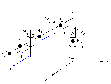
Parameter Database ID Parameter Name Values 16066
Dynamic feedforward enable
1
16067
Dynamic feedforward mass, kg
M1, M2, M3, M4, Mp
16068
Dynamic feedforward COM l1, mm
0, l12, l13, l14, l1p
16069
Dynamic feedforward COM l2, mm
0, 0, 0, 0, 0
16070
Dynamic feedforward rated torque, N-m
<filled in based on axis drives>
16071
Dynamic feedforward default %payload
Any value from 0 to 100
16072
Dynamic feedforward motor/gear inertia, kg-mm^2
Motor and gear box inertias as seen by the axes
Mp and l1p define the maximum mass of the payload and the position of this mass relative to the 4th axis. M4 and l14 represent both the tool mounting flange and the tool.
If the Enhanced DFF Model bit is set in the "Robot type special option flags", the following diagram and table illustrate how the DFF constants are defined for this robot.
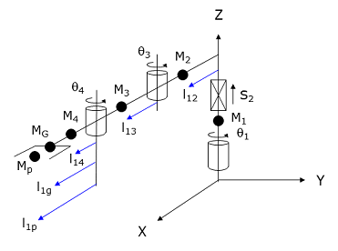
Parameter Database ID Parameter Name Values 16066
Dynamic feedforward enable
1
16067
Dynamic feedforward mass, kg
M1, M2, M3, M4, MG, MP
16068
Dynamic feedforward COM l1, mm
0, l12, l13, l14, l1g, l1p
16069
Dynamic feedforward COM l2, mm
l21, 0, 0, 0, 0
16070
Dynamic feedforward rated torque, N-m
<filled in based on axis drives>
16071
Dynamic feedforward default %payload
Any value from 0 to 100
16072
Dynamic feedforward motor/gear inertia, kg-mm^2
Motor and gear box inertias as seen by the axes
MG and l1g represent the mass and distance to the centroid of the tool. Mp and l1p define the maximum mass of the payload and the position of this mass relative to the q4 axis. The maximum mass of the payload is dynamically reduced by the setting of the Robot.Payload instruction. The l21 dimension is used for computing the rotational inertia when M1 is rotated about it own axis. That is, M1*l21^2 times the acceleration of q1 is added to the other computed DFF torques for the first motor.
Additional Considerations
The first element of the Robot.Custom property defines which of the two yaw axes is factored into the Cartesian control of the robot (i.e. is the primary yaw axis). Specifically,
Robot.Custom(1) = 0     ' Selects the lower yaw (q4) as primary
Robot.Custom(1) = 1     ' Selects the upper yaw (q5) as primary
Whenever you modify the Robot.Custom property, execution of the thread will automatically pause until the robot has come to a stop and the change can be put into effect.
To move the secondary yaw and/or the independent Extra axis and/or the linear traverse rail and/or the second independent Extra axis during the next motion of the primary axes to a Cartesian Location, execute the Move.Extra method. If this method is not invoked and the next motion is to a Cartesian Location, the position of the secondary yaw and/or independent Extra axis and/or the linear traverse will not be altered. The following illustrates the use of Move.Extra.
Move.Extra(30)   ' Move secondary axis to 30 deg during next motion
Move.Loc(Location.XYZValue(300,0,100),pf1) ' Move primary arms tool
The yaw axes and the two independent Extra axis and the linear traverse can also be simultaneously moved by performing a motion to an Angles Location. The value of the location will explicitly define the final position for all axes.
As another means of controlling the secondary yaw axis, the position of this axis can automatically be set to the same position as the primary axis (plus a fixed angular offset) when the destination of a joint interpolated motion or each setpoint of a Cartesian motion is computed. This mode is very useful for moving both grippers along a straight line path to simultaneously pick or place two parts.
The following illustrates how to enable and disable this mode:
Robot.Custom(2) = 1        ' Enable synchronization of yaw axes
Robot.Custom(3) = offset   ' Specifies offset angle added to primary yaw
        :
Robot.Custom(2) = 0        ' Disable synchronization of yaw axes
This mode requires that the two yaw axes be in alignment at the start of any Cartesian motion. After this mode has been enabled, it is the responsibility of the application program to execute a joint interpolated motion to a Cartesian Location to force the two yaw axes into alignment before a Cartesian motion is executed. If the yaw axes are not in alignment at the start of a Cartesian motion or during World or Tool manual control, the following error will be generated:
-1056 Incompatible robot position
Whenever you modify the Robot.Custom property to set the parameters for this mode, execution of the thread will automatically pause until the robot has come to a stop and the change can be put into effect.