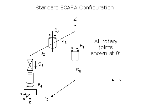
This module controls a 4-Axis or 3-Axis or 2-Axis SCARA (Selective Compliance Assembly Robot Arm) mechanism that consists of an inner link that rotates about the World Z-axis, connected to an outer link that rotates about a Z elbow joint, which in turn is connected to a wrist axis that moves up and down and optionally rotates about Z. The first two rotary axes position the robot's end-effector in the X-Y plane. The combination of the three rotary axes governs the orientation of the gripper about the Z-axis. The linear axis determines the gripper's vertical position. This geometric configuration is the most popular design for vertical assembly and small parts pick-and-place operations due to its simplicity, high speed and precision.
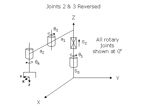
As an option, this kinematic module can be configured to switch the second and third axes. In this case, the linear axis moves the inner and outer links up and down rather than just the wrist. For consistency with standard conventions, if the linear axis is configured as the second axis, a positive change in the linear axis position moves the links up in World Z. If the linear axis is configured as the third axis, a positive change in the axis position moves the wrist down in World Z.
Kinematics Module Number and Required Software License
Module number to be entered into the "Robot type" (DataID 116): 10
Required software kinematic license (entered using the web interface panel Utilities > Controller Options if not already installed): Advanced Kinematics.
Kinematic Model
Axis Optional Max Range Description 1: q1
No
+/- 359.9°
Rotary axis that rotates the links of the robot about the World Z-axis. A positive change in the axis angle results in a positive rotation about the World Z-axis. The center of this axis' travel can be arbitrarily set, e.g. 0 or 45 or 180 or -135 degrees.
2: q2
No
+/- 359.9°
Rotary axis that rotates the outer link about the World Z-axis. A positive change in the axis angle results in a positive rotation about the World Z-axis. The center of this axis' travel can be arbitrarily set, e.g. 0 or 180 or -180 degrees. So a range of travel of -360 to 360 degrees or 0 to 720 degrees or -720 to 0 degrees are all permitted.
3: S3
Yes
Max double precision range
Linear axis that moves the robot in the direction of the World Z-axis. A positive change in the axis position results in a movement in the direction of the negative World Z-axis (down).
4: q4
Yes
Unlimited but typically set to +/- 359.9°
Rotary axis that rotates the end-effector about World Z-axis. A positive change in the axis angle results in a negative rotation about the World Z-axis. The center of this axis' travel can be arbitrarily set, although it is typically centered about 0, 180 or -180 degrees.
Parameter Database Values
The following table describes the Parameter Database values that are utilized to configure the kinematic module. Standard motion control parameters such as servo tuning values, limit stops, the homing specification, etc are not included in the table.
Parameter Database ID Parameter Name Description 2000
Number of axes
Must be set to 4 or 3 or 2.
2001
Split-axis mask
Not applicable.
2003
Axis mask
Bit mask indicating the specific axes that are to be controlled. The least significant bit (1) corresponds to the first rotary axis, q1. For example, if all 4 axes are to be controlled, this value should be set to 15 (binary 1111). If the final rotary axis, q4, is not configured, this value should be set to 7 (binary 0111).
2005
Motor linearity compensation
Not supported.
2006
Robot type special option flags
Bit mask that enables special features of the kinematic module. These bits are interpreted as follows:
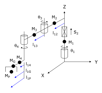
&H01: Reverses the second and third axes. If set, the second axis controls the linear axis that moves the inner and outer links up and down. In this case, a positive change in the linear axis position moves the links in the positive direction of the World Z-axis.
&H02: If set, a 2x2 motor coupling matrix is used to compensate for mechanical coupling between the last 2 joints (typically axes 3 & 4). If not set, no motors are mechanically coupled and the conversions from axis positions to motor positions are specified by single scalar values.
&H100: If set, enables the Enhanced Dynamic Feedforward (DFF) model. For this module, the enhanced model includes separate specifications for the gripper and payload, and when the second axis is linear, an explicit definition for the rotational inertia of the Z-axis mass about its axis.2701 / 2703
100% Cartesian speeds and accels
Value 1: Cartesian 100% linear speed and acceleration of the robot's end-effector measured along any vector in X, Y and Z.
Value 2: Cartesian 100% rotation speed and acceleration of the end-effector about the world Z-axis. (Only valid for robots that include the final rotary axis, q4.)
Values 3-n: Not used.
16050
Kinematic dimensional constants
Value 1 (S0): Vertical (Z) offset of the tool relative to the origin of the World coordinate system when joint 3 (S3) is at its zero position. Can be arbitrary set by the robot designer to establish the height of the World coordinate system.
Value 2 (a1): Length of the inner link measured from the axis of q1 to that of q2.
Value 3 (a2): Length of the outer link measured from the axis of q2 to that of q4.
Values 4-n: Not used.
16051
Tool set at restart
When the controller is restarted, this specifies the initial value for the position and orientation of the robot's tool center point relative to the wrist joint, q4. For most simple tools, only the length of the tool needs to be defined by setting this parameter to: 0, 0, tool_length, 0, 0, 0.
16052
Base set at restart
When the controller is restarted, this defines how the base of the robot is positioned and oriented relative to the World coordinate system. Normally, this parameter is set to 0, 0, 0, 0, 0, 0.
Robot Configuration ("Config") Parameters
This kinematic module makes use of the following Location Config property flags to control how Cartesian positions and orientations are converted to joint angles since multiple sets of joint angles are possible:
GPL_Righty, GPL_Lefty, GPL_Single.
Special Compensation
This kinematic module does support "Continuous Turn Axes" for the the last rotary axis: q4.
If a bit is set in the "Robot type special option flags" (DataID 2006), mechanical coupling between the last two axes (typically joints 3 and 4) can be compensated by a 2x2 motor coupling matrix. If motor coupling exists, the last rotary axis can still be configured for continuous turns so long as a change in the position of the 4th axis does not alter the position of the 3rd motor.
This kinematic module does not support "Linearity Compensation" or "Split-Axis Control".
This kinematic module does support "Dynamic Feedforward" compensation (DFF). This kinematic module includes the full DFF dynamic model for this robot with axes 2 & 3 in their standard configuration or switched. This model can compensate for the effects of coupled inertial acceleration, centripetal and Coriolis forces, and gravity loading.
NOTE: DFF is not supported for the 2-axes configuration.
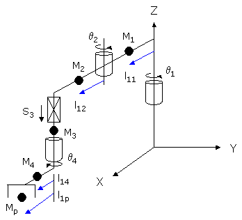
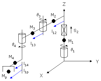
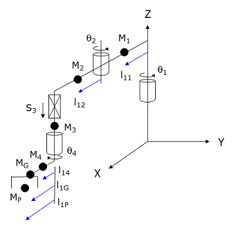
If the Enhanced DFF Model bit is not set in the "Robot type special option flags", the following diagrams and tables illustrate how the DFF constants are defined for this robot in the two configurations.
Parameter Database ID Parameter Name Values 16066
Dynamic feedforward enable
1
16067
Dynamic feedforward mass, kg
M1, M2, M3, M4, Mp
16068
Dynamic feedforward COM l1, mm
l11, l12, 0, l14, l1p
16069
Dynamic feedforward COM l2, mm
0, 0, 0, 0, 0
16070
Dynamic feedforward rated torque, N-m
<filled in based on axis drives>
16071
Dynamic feedforward default %payload
Any value from 0 to 100
16072
Dynamic feedforward motor/gear inertia, kg-mm^2
Motor and gear box inertias as seen by the axes
Parameter Database ID Parameter Name Values 16066
Dynamic feedforward enable
1
16067
Dynamic feedforward mass, kg
M1, M2, M3, M4, Mp
16068
Dynamic feedforward COM l1, mm
0, l12, l13, l14, l1p
16069
Dynamic feedforward COM l2, mm
0, 0, 0, 0, 0
16070
Dynamic feedforward rated torque, N-m
<filled in based on axis drives>
16071
Dynamic feedforward default %payload
Any value from 0 to 100
16072
Dynamic feedforward motor/gear inertia, kg-mm^2
Motor and gear box inertias as seen by the axes
For both configurations, Mp and l1p define the maximum mass of the payload and the position of this mass relative to the 4th axis. M4 and l14 represent both the tool mounting flange and the tool. If the robot's tool is centered on the 4th axis and is not horizontally offset, then l14 and l1p should be set to 0.
If the Enhanced DFF Model bit is set in the "Robot type special option flags", the following diagrams and tables illustrate how the DFF constants are defined for this robot in the two configurations.
Parameter Database ID Parameter Name Values 16066
Dynamic feedforward enable
1
16067
Dynamic feedforward mass, kg
M1, M2, M3, M4, MG, MP
16068
Dynamic feedforward COM l1, mm
l11, l12, 0, l14, l1G, l1P
16069
Dynamic feedforward COM l2, mm
0, 0, 0, 0, 0
16070
Dynamic feedforward rated torque, N-m
<filled in based on axis drives>
16071
Dynamic feedforward default %payload
Any value from 0 to 100
16072
Dynamic feedforward motor/gear inertia, kg-mm^2
Motor and gear box inertias as seen by the axes
Parameter Database ID Parameter Name Name 16066
Dynamic feedforward enable
1
16067
Dynamic feedforward mass, kg
M1, M2, M3, M4, MG, MP
16068
Dynamic feedforward COM l1, mm
0, l12, l13, l14, l1G, l1P
16069
Dynamic feedforward COM l2, mm
l21, 0, 0, 0, 0
16070
Dynamic feedforward rated torque, N-m
<filled in based on axis drives>
16071
Dynamic feedforward default %payload
Any value from 0 to 100
16072
Dynamic feedforward motor/gear inertia, kg-mm^2
Motor and gear box inertias as seen by the axes
For both configurations, MG and l1G represent the mass and distance to the centroid of the tool. MP and l1P define the maximum mass of the payload and the position of this mass relative to the 4th axis. The maximum mass of the payload is dynamically reduced by the setting of the Robot.Payload instruction. If the robot's tool is centered on the 4th axis and is not horizontally offset, then l14, l1G and l1P should be set to 0. For the configuration where the second axis is linear, the l21 dimension is used for computing the rotational inertia when M1 is rotated about it own axis. That is, M1*l21^2 times the acceleration of q1 is added to the other computed DFF torques for the first motor.
Additional Considerations
This kinematic module does not utilize the Custom Kinematic Parameters accessed by Robot.Custom.
This kinematic module does not have any extra, independent axes so Move.Extra has no affect.