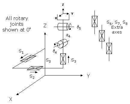
This module controls an X/Y/Z table on which is mounted two rotary axes that tip and tilt the robot's end-effector. In addition, this model includes three optional "Extra" independent axes. This module can be optionally configured to be used with any combination of 1 to 8 axes. For example, this module can control a single X-axis, an XYZ table with up to 3 independent axes, an XYZ table with just a tip or tilt axis, or the full 5 degree-of-freedom table with both the tip and the tilt axes and 3 independent axes. This robot configuration is often used for a table that is holding a work piece that is being processed or to model a CNC machine. For example, this configuration is encountered in arc welding applications where the table holds the part to be welded and is tipped and tilted to present the weld point.
The first 3 axes of this module are linear and move the robot in X, Y, and Z. The fourth (tip) axis is rotary and turns the end-effector about the positive World X direction. The fifth (tilt) axis is rotary and turns the end-effector about the positive Tool Y direction. The final three axes can synchronize the motion of either linear or rotary independent axes with the robot. However, these independent axes do not factor into the computation of the position and orientation of the robot.
Kinematics Module Number and Required Software License
Module number to be entered into the "Robot type" (DataID 116): 13
Required software kinematic license (entered using the web interface panel Utilities > Controller Options if not already installed): Advanced Kinematics.
Kinematic Model
Axis Optional Max Range Description 1: S1
Yes
Max double precision range
Linear axis that moves the robot in the direction of the World X-axis. A positive change in the axis position results in a movement in the direction of the positive World X-axis.
2: S2
Yes
Max double precision range
Linear axis that moves the robot in the direction of the World Y-axis. A positive change in the axis position results in a movement in the direction of the positive World Y-axis.
3: S3
Yes
Max double precision range
Linear axis that moves the robot in the direction of the World Z-axis. A positive change in the axis position results in a movement in the direction of the negative World Z-axis.
4: q4
Yes
Several rotations but typically less than +/- 359.9°
Rotary "tip" axis that rotates the end-effector about the direction of the World X-axis. A positive change in the axis angle results in a positive rotation in the direction of the World X-axis. The center of this axis' travel can be arbitrarily set, although it is typically centered about 0 degrees.
5: q5
Yes
Several rotations but typically less than +/- 359.9°
Rotary "tilt" axis that rotates the end-effector about the direction of the Tool Y-axis. A positive change in the axis angle results in a positive rotation in the direction of the Tool Y-axis. The center of this axis' travel can be arbitrarily set, although it is typically centered about 0 degrees.
6: S6
Yes
Unlimited
Optional independent (Extra) axis.
7: S7
Yes
Unlimited
Optional independent (Extra) axis.
8: S8
Yes
Unlimited
Optional independent (Extra) axis.
Parameter Database Values
The following table describes the Parameter Database values that are utilized to configure the kinematic module. Standard motion control parameters such as servo tuning values, limit stops, the homing specification, etc are not included in the table.
Parameter Database ID Parameter Name Description 2000
Number of axes
Can be set from 1 to 8.
2001
Split-axis mask
Not supported.
2003
Axis mask
Bit mask indicating the specific axes that are to be controlled. The least significant bit (1) corresponds to the X axis. For example, if all 5 axes are to be controlled, this value should be set to 31 (binary 11111). If only the X and Z axes are configured, this value should be set to 5 (binary 0101). The 6th, 7th, and 8th bits (binary 11100000) configure the Extra independent axes.
2005
Motor linearity compensation
Not supported.
2006
Robot type special option flags
Not applicable.
2701 / 2703
100% Cartesian speeds and accels
Value 1: Cartesian 100% linear speed and acceleration of the robot's end-effector measured along any vector in X, Y and Z.
Value 2: Cartesian 100% rotational speed and acceleration of robot's end-effector about the direction of the first rotary axis. Normally set equal to the 100% joint speed and acceleration of the tip axis (if configured) or the tilt axis (if the tip axis is not configured) or the 1st Extra axis (if it is configured but the tip and tilt are not) or otherwise ignored.
Value 3: Cartesian 100% rotational speed and acceleration of robot's end-effector about the direction of the second rotary axis. Normally set equal to the 100% joint speed and acceleration of the tilt axis (if both the tip and tilt are configured) or the 1st Extra axis (if it is configured and either the tip or the tilt axes are configured) or the 2nd Extra axis (if it is configured and both the tip and tilt are not configured) or otherwise ignored.
Value 4: Cartesian 100% rotational speed and acceleration of the 1st Extra axis (if both the tip and tilt are configured) or the 2nd Extra axis (if it is configured and either the tip or the tilt axes are configured) or the 3rd Extra axis (if it is configured and both the tip and tilt are not configured) or otherwise ignored.
Value 5: Cartesian 100% rotational speed and acceleration of the 2nd Extra axis (if both the tip and tilt are configured) or the 3rd Extra axis (if it is configured and either the tip or the tilt axes are configured) or otherwise ignored.
Value 6: Cartesian 100% rotational speed and acceleration of the 3rd Extra axis if the tip and tilt and all three Extra axes are configured.
Values 7-n: Not used.
16050
Kinematic dimensional constants
Value 1 (S0): Z offset for the base of the robot. Increasing this value logically moves the robot up in Z. For example, if this value is 0, when the Z and the tip axes are at their 0 positions, the tool tip will be at a World Z value equal to the offset a4. Alternately, if this parameter is 100, when the Z and the tip axes are at their 0 positions, the tool tip will be at a World Z value of a4+100 millimeters.
Value 2 (a4): Offset distance between the q4 (tip) and q5 (tilt) axes of rotation.
Values 3-n: Not used.
16051
Tool set at restart
When the controller is restarted, this specifies the initial value for the position and orientation of the robot's tool center point relative to the end of the Z-axis. For most simple tools, only the length of the tool needs to be defined by setting this parameter to: 0, 0, tool_length, 0, 0, 0.
16052
Base set at restart
When the controller is restarted, this defines how the base of the robot is positioned relative to the World coordinate system. Normally, this parameter is set to 0, 0, 0, 0, 0, 0.
NOTE: The Base property can only be used to translate the origin of this robot and cannot be used to rotate it.
Robot Configuration ("Config") Parameters
This kinematic module makes use of the following Location Config property flags to control how Cartesian positions and orientations are converted to joint angles:
None
Special Compensation
This kinematic module does not support "Continuous Turn Axes" capability for any axes.
This kinematic module does not support "Motor Coupling", "Linearity Compensation" or "Split-Axis Control".
This kinematic module does not support "Dynamic Feedforward" compensation (DFF).
Additional Considerations
This kinematic module does not utilize the Custom Kinematic Parameters accessed by Robot.Custom.
To move the extra axes during the next motion of the primary axes to a Cartesian Location, execute the Move.Extra method. If this method is not invoked and the next motion is to a Cartesian Location, the positions of the extra axes will not be altered. The following illustrates the use of Move.Extra.
Move.Extra(30)      ' Move 1st extra axis to 30mm during next motion
Move.Loc(Location.XYZValue(300,0,100),pf1) ' Move primary and 1st extra axis
Both the primary and the extra axes can also be simultaneously moved by performing a motion to an Angles Location. The value of this location will explicitly define the final position for all axes.