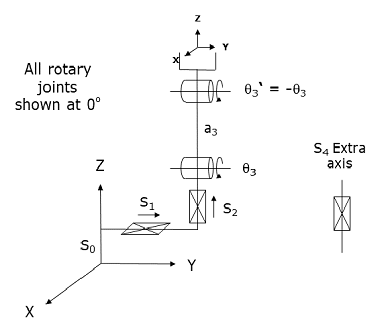
This module controls an YZR mechanism that has an additional 4th "extra" servoed axis. The rotary axis for this robot is mechanically coupled to the tool output flange such that the orientation of the tool remains fixed as the rotary axis changes position. So, the rotary axis translates the tool in the X-Z plane without affecting the orientation of the tool and this robot yields the same motions as a conventional XYZ Cartesian robot.
The "extra" axis can either be rotary or linear and can synchronize the operation a servo gripper or some other device with the robot. However, this fourth is not considered when computing the Cartesian position of the robot. To position the 4th axis, a program must either move the robot to an Angles Location or use the Move.Extra method.
Kinematics Module Number and Required Software License
Module number to be entered into the "Robot type" (DataID 116): 23
Required software kinematic license (entered using the web interface panel Utilities > Controller Options if not already installed): Advanced Kinematics.
Kinematic Model
Axis Optional Max Range Description 1: S1
Yes
Max double precision range
Linear axis that moves the robot in the direction of the World Y-axis. A positive change in the axis position results in a movement in the direction of the positive World Y-axis.
2: S2
No
Max double precision range
Linear axis that moves the robot in the direction of the World Z-axis. A positive change in the axis position results in a movement in the direction of the positive World Z-axis.
3: q3
No
Unlimited but typically set to +/- 89.9°
Rotary axis that translates the end-effector in the X-Z plane. From zero degrees, a positive change in this axis moves the end-effector in the positive World X-axis direction and moves the tool somewhat in the negative World Z-axis direction. The center of this axis' travel can be arbitrarily set, although it is typically centered about 0, 180 or -180 degrees.
4: S4
Yes
Max double precision range
Rotary or linear axis that controls an extra axis that does not factor into the computation of the Cartesian Location of the robot.
Parameter Database Values
The following table describes the Parameter Database values that are utilized to configure the kinematic module. Standard motion control parameters such as servo tuning values, limit stops, the homing specification, etc are not included in the table.
Parameter Database ID Parameter Name Description 2000
Number of axes
Can be set from 2 to 4.
2001
Split-axis mask
Not supported.
2003
Axis mask
Bit mask indicating the specific axes that are to be controlled. The least significant bit (1) corresponds to the Y-axis. The most significant bit corresponds to the extra axis. For example, if all 4 axes are to be controlled, this value should be set to 15 (binary 1111). If only the Z and rotary axis are configured, this value should be set to 6 (binary 0110).
2005
Motor linearity compensation
Not supported.
2006
Robot type special option flags
Not applicable.
2701 / 2703
100% Cartesian speeds and accels
Value 1: Cartesian 100% linear speed and acceleration of the robot's end-effector measured along any vector in X, Y and Z.
Value 2: 100% speed and acceleration of the extra axis. Normally, this is set equal to the 100% joint speed and acceleration of the extra axis.
Values 3-n: Not used.
16050
Kinematic dimensional constants
Value 1 (S0): Z offset for the base of the robot. Increasing this value logically moves the robot up in Z. For example, if this value is 0, when the Z-axis is at its 0 position, the center of rotation of the rotary axis will be at a World Z value of 0. Alternately, if this parameter is 100, when the Z-axis is at its 0 position, the center of rotation of the rotary axis will be at a World Z value of 100 millimeters.
Value 2 (a3): Length of the link drive by the rotary axis q3.
Values 3-n: Not used.
16051
Tool set at restart
When the controller is restarted, this specifies the initial value for the position and orientation of the robot's tool center point relative to the end of the Z-axis. For most simple tools, only the length of the tool needs to be defined by setting this parameter to: 0, 0, tool_length, 0, 0, 0.
16052
Base set at restart
When the controller is restarted, this defines how the base of the robot is positioned and oriented relative to the World coordinate system. Normally, this parameter is set to 0, 0, 0, 0, 0, 0.
Robot Configuration ("Config") Parameters
This kinematic module makes use of the following Location Config property flags to control how Cartesian positions and orientations are converted to joint angles:
GPL_Above, GPL_Below
When this robot is in the "Above" configuration, q3 will range from +/- 90 degrees.
Special Compensation
This kinematic module does not support "Continuous Turn Axes" capability for any axes.
This kinematic module does not support "Motor Coupling", "Linearity Compensation" or "Split-Axis Control".
This kinematic module does not support "Dynamic Feedforward" compensation (DFF).
Additional Considerations
This kinematic module does not utilize the Custom Kinematic Parameters accessed by Robot.Custom.
To move the extra (4th) axis during the next motion of the primary axes to a Cartesian Location, execute the Move.Extra method. If this method is not invoked and the next motion is to a Cartesian Location, the position of the extra axis will not be altered. The following illustrates the use of Move.Extra.
Move.Extra(30)      ' Move extra axis to 30mm during next motion
Move.Loc(Location.XYZValue(300,0,100),pf1) ' Move primary and extra axis
Both the primary and the extra axes can also be simultaneously moved by performing a motion to an Angles Location. The value of this location will explicitly define the final position for all axes.