
The high voltage, high performance processor board (HVCPU) has a number of hardware jumpers that determine the configuration of some system hardware and software functions and some LEDs that indicate the status of the board. Depending upon the type of jumper, there may be two or more jumper posts. Posts are tied (shorted) together using black jumper plugs. The two wide jumper posts for configuring the RS-485 daisy-chain termination are shown in Figure 17-24.
The locations for each of the sets of jumpers and LEDs are illustrated in Figure 17-25 and are identified by stenciled labels on the surface of the HVCPU board.
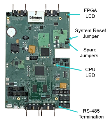
Figure 17-25: Locations for Jumpers and LEDs
Table 17-10 describes each of these LEDs and sets of jumpers and how the pins must be shorted ("jumpered") in order to set a specific configuration. When a direction (e.g., left versus right) is described, it is with respect to the HVCPU board oriented as shown in Figure 17-25.
| Jumpers | Description | Setting |
|---|---|---|
|
J11/J10 Spare Jumpers |
There are two sets of three posts whose use is currently undefined. For each set, when the center and right post is jumpered, the input is OFF. When the center and left post is jumpered, the input is ON. As shipped from the factory, these jumpers are set to OFF. |
Not currently used. |
|
J9 System Reset Jumper |
If a jumper is installed on these two posts, when the system is restarted, the default configuration files (*.PAC) are applied instead of the standard files. This setting is utilized if a configuration file becomes corrupted or a setting inadvertently makes the system unusable. As shipped from the factory, this jumper is not installed. |
Install jumper J9 to reset the system. |
|
J2 RS-485 Termination |
This jumper controls how the RS-485 serial communication lines are terminated. For reliable communications, if the controller is at the end of an RS-485 daisy chain, this jumper should be installed to terminate the line. If the controller is in the middle of an RS-485 daisy chain, this jumper must be uninstalled to disable the termination. As shipped from the factory, this jumper is installed and the RS-485 lines are terminated. |
Install jumper J2 to terminate the RS-485 communication lines. |
|
CPU/Status LED |
This is a red and green LED that blinks different patterns to indicate the operational status of the controller. See the Status LED and Status Output Signal section of this manual for information on how to interpret the red/green blinking patterns. |
|
|
FPGA LED |
This is a diagnostic LED that is connected to the FPGA chip. When the HVCPU is powered up and loading of the firmware into the FPGA is completed, this LED will blink green 4 times and then remain off. |
|